Bench testing of comparable 0603 MLCCs shows many failure modes and parameter drift emerging above 85°C and in high-humidity conditions, so reading the 06033A680K4T2A datasheet carefully is essential before sign-off. This guide breaks the part’s identification, core specs, reliability test results, and practical electrical and mechanical limits to speed component selection and qualification.
1 Part Overview: Identification, Package and Intended Uses
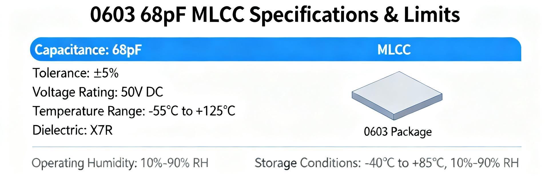
Part ID decoded (capacitance, tolerance, voltage)
Point: The part number encodes nominal capacitance, tolerance, voltage rating and package.
Evidence: manufacturer datasheets typically map the middle digits to capacitance and trailing letters to tolerance/voltage.
Explanation: For 06033A680K4T2A, the nominal capacitance is 68 pF, tolerance code K (±10%), rated DC voltage commonly 25 V, and package code 0603 (1608 metric).
| Capacitance | Tolerance | Rated DC Voltage | Package |
|---|---|---|---|
| 68 pF | K (±10%) | 25 V | 0603 (1.6 × 0.8 mm) |
Typical application scenarios
Point: Small 0603 68 pF MLCCs are commonly used for bypassing, RF tuning, and compact decoupling.
Evidence: datasheet application notes list bypass and tuning uses for low-capacitance parts; designers favor 0603 where board area is limited.
Explanation: This part is ideal in space-constrained analog/RF paths and local decoupling; it is less suitable where high voltage margin, large capacitance, or extreme damp/thermal reliability are required.
2 Key Electrical Specs for 06033A680K4T2A
Core electrical parameters (what to report)
Point: Key specs to capture are nominal capacitance, tolerance, rated DC voltage, dielectric class, temperature coefficient, dissipation factor (DF), and insulation resistance (IR).
Evidence: manufacturer tables list typical vs. max values per parameter.
Explanation: Record both typical and guaranteed maximums—e.g., capacitance ± tolerance, DF typical and maximum at target frequency, and IR specified at given test voltage—to set pass/fail limits for incoming inspection.
| Parameter | Typical | Qualified Limit |
| Capacitance | 68 pF | ±10% |
| Dissipation Factor | ≤0.5% (freq-dependent) | Manufacturer max at test freq |
| Insulation Resistance | High (manufacturer-specified) | Spec sheet value at test V |
Frequency and temperature behavior
Point: Capacitance and DF vary with frequency and temperature; dielectric class drives stability.
Evidence: datasheets include C vs. T and DF vs. frequency curves for NP0/C0G vs. X7R-type dielectrics.
Explanation: For timing or RF, favor NP0/C0G for minimal drift; for bulk decoupling accept X7R with higher DF and capacitance shift—always reference the part’s curves for your operating band and temperature envelope.
3 Test Data, Reliability Results & Absolute Limits
Environmental and mechanical test results
Point: Datasheets list qualification tests such as temperature cycling, humidity soak, thermal shock, mechanical shock/vibration and solderability.
Evidence: Each test entry specifies conditions (temperature range, dwell time, cycles) and acceptance criteria.
Explanation: Capture test durations and pass/fail metrics from the datasheet and verify supplier lot reports for those same procedures when approving parts for production.
Electrical limits and failure modes
Point: Important electrical limits include insulation resistance minimums, dielectric breakdown voltages, and dissipation factor upper limits; aging/stability thresholds may be listed.
Evidence: Manufacturer tables show IR at test voltage, breakdown voltage margins and DF maxima.
Explanation: Watch for common failure signatures—IR collapse, DF rise, capacitance shift—and request supplier test data that demonstrate margins at your operating voltage and humidity conditions.
4 Application Guidance: Design, Derating & Soldering
Circuit-level guidance and derating rules
Point: Apply voltage and temperature derating to extend life and reduce failures.
Evidence: Design recommendations in datasheets and reliability guides advise reduced applied voltage and derating at elevated temperatures.
Explanation: A conservative rule: limit continuous applied voltage to 50–80% of rated voltage at ambient; at elevated temperatures reduce further. For RF/timing, account for dielectric tempco in tolerance budgeting.
PCB mounting, reflow and handling recommendations
Point: Land pattern, paste amount and reflow profile greatly affect tombstoning and microcrack risk.
Evidence: Datasheets provide recommended land patterns and maximum reflow peak temperatures.
Explanation: Use recommended pad sizes, controlled paste volume, single-peaked reflow within specified profile, and minimize mechanical flex near 0603 parts; follow ESD handling precautions listed by the manufacturer.
5 Alternatives, Equivalents and Selection Trade-offs
When to choose a different dielectric or voltage rating
Point: Dielectric choice trades stability against capacitance density and cost.
Evidence: NP0/C0G offers superior stability and low DF; X7R/Y5V yield higher capacitance per volume but larger drift.
Explanation: For precision timing or RF use NP0/C0G; for bulk decoupling where size matters and drift is tolerable, choose X7R or larger package/higher voltage to improve reliability.
Cross-reference checklist for substitutions
Point: Substitutions must match critical electrical and physical parameters.
Evidence: Typical cross-reference checklists require matching capacitance, tolerance, voltage rating, dielectric tempco and size.
Explanation: Ensure capacitance and tolerance, voltage rating and dielectric class match; acceptable variations include termination finish or packaging format. Long-tail search terms to consider when sourcing: "0603 68pF 25V MLCC alternative".
6 Procurement, Qualification & On-board Testing Checklist
Datasheet items to verify before purchase
Point: Validate datasheet revision, lot traceability, packing, and compliance statements.
Evidence: Procurement checklists call for revision numbers, RoHS/REACH declarations and available test reports.
Explanation: Always request the latest revision of the manufacturer datasheet, lot-level certificates of conformance, and any supplier test certificates showing the qualification tests used for acceptance.
In-house qualification tests to run
Point: Incoming inspection should include visual, dimensional, electrical and accelerated environmental tests.
Evidence: QA programs typically specify sample sizes and thresholds tied to datasheet limits.
Explanation: Run sample capacitance and DF at operating frequency/temperature, IR measurement at specified test voltage, and an accelerated humidity/temperature soak; set pass/fail to datasheet guaranteed limits and size samples per your AQL.
Frequently Asked Questions
Is the 06033A680K4T2A suitable for RF timing applications?
The suitability depends on the listed dielectric class and DF in the datasheet. If specified as NP0/C0G with very low DF and flat C vs. T/frequency curves, it is suitable for RF timing. If it’s a class 2 dielectric (e.g., X7R), expect higher DF and capacitance drift—verify datasheet curves before use.
What derating rule should be applied to 06033A680K4T2A in high-temperature designs?
Derate operating voltage and account for temperature coefficients shown in the datasheet. A practical rule is to limit continuous applied voltage to 50–80% of rated voltage at ambient and reduce further at elevated temperatures; always confirm with the supplier’s C vs. T and IR data for your max operating temp.
Which datasheet limits are most critical to request from suppliers for 06033A680K4T2A?
Mandatory limits to verify are insulation resistance at test voltage, DF at operating frequency, C tolerance at temperature extremes, and solderability/test-for-reflow results. Request lot-level test reports and qualification certificates that explicitly show these metrics matching the published datasheet limits.
