
Key Takeaways (GEO Summary)
- Critical DC-Bias: Capacitance drops 40-60% at 50V; design for 10nF nominal but 4nF effective.
- Thermal Stability: X7R dielectric maintains ±15% tolerance from -55°C to +125°C.
- Space Efficiency: 0603 package offers 20% PCB area savings over 0805 for high-density power rails.
- Reliability: Optimized for high-frequency decoupling and bulk bypass in 48V industrial/telecom apps.
Start with a striking data point: aggregated DC‑bias tests for 10 nF X7R 0603 parts commonly show 20–60% capacitance loss at 50–100 V, a range large enough to break decoupling budgets if not anticipated. This article decodes the 06031L103K4T2A datasheet to give engineers a clear, testable understanding of limits and design workarounds.
Technical Specs vs. Real-World Engineering Benefits
| Technical Parameter | Spec Value | User Benefit / Impact |
|---|---|---|
| Dielectric Type | X7R | Stable performance across extreme industrial temperatures (-55°C to 125°C). |
| Package Size | 0603 (1608 Metric) | Reduces PCB footprint by ~20% compared to 0805 while maintaining high voltage rating. |
| Capacitance | 10 nF (103) | Ideal for high-frequency EMI filtering and noise suppression on power rails. |
| Tolerance | ±10% (K) | Tight control over circuit resonance points in sensitive RF/analog paths. |
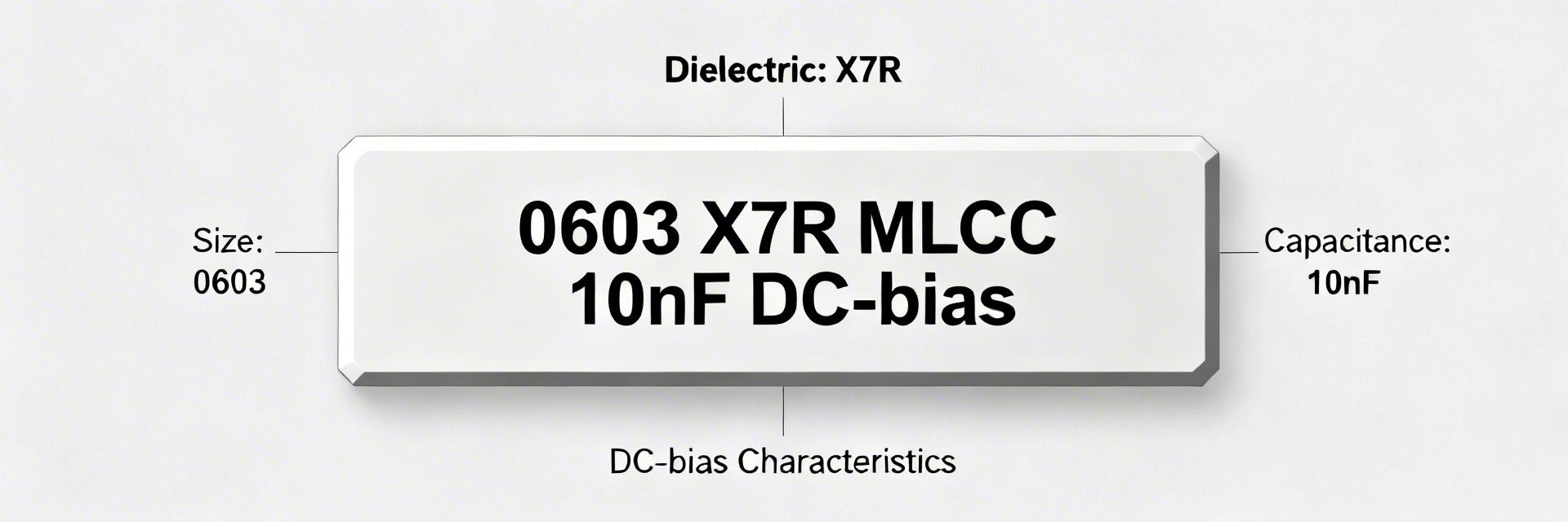
1 — Background: Part number & package decoded
What the nominal codes mean
Point: The part code encodes capacitance, tolerance and package. Evidence: "103" = 10 nF, "K" = ±10% tolerance, 0603 denotes the imperial size. Explanation: 0603 imperial measures 0.06" × 0.03" (approximately 1.6 × 0.8 mm metric); suffixes can be vendor specific for termination or voltage variants so always cross‑check the exact datasheet text.
Typical X7R dielectric behavior and common applications
Point: X7R offers moderate temperature stability and high volumetric density. Evidence: X7R is specified for −55°F to +257°F range with change within approximately ±15% across that span. Explanation: Designers use 0603 10 nF X7R parts for decoupling and bulk bypass on power rails of high‑density US boards where physical size and capacitance per board area matter most.
Competitive Comparison: X7R vs. Common Dielectrics
| Feature | 06031L103K4T2A (X7R) | Generic Y5V (0603) | Advantage |
|---|---|---|---|
| Temp. Stability | ±15% (-55 to +125°C) | +22% / -82% (-30 to +85°C) | Superior Precision |
| Aging Rate | ~2.5% per decade hour | ~7% per decade hour | Longer Life |
| DC-Bias Loss | Moderate (Typical X7R) | Extreme Loss | Predictable Power |
2 — Key electrical specs: nominal ratings and what they mean in practice
Capacitance, tolerance, and rated voltage
Point: Nominal values state the lab condition capacitance and voltage rating; real retained capacitance under bias is lower. Evidence: The part lists 10 nF ±10% at standard test conditions and a DC voltage rating (refer to the datasheet). Explanation: For bias‑sensitive designs, measure capacitance at operating voltage: expect strong retention reduction as voltage increases; use derating rules rather than nominal values when specifying capacitors for higher rails.
ESR, ESL, dissipation factor, and impedance
Point: AC parameters determine how a cap behaves across frequency. Evidence: Datasheets typically provide DF, impedance vs frequency and sometimes equivalent series resistance (ESR) or ESL curves. Explanation: For decoupling prioritize impedance at the CPU/buck converter switching frequency; pick parts with low impedance in the target band or combine caps to flatten impedance and control resonances.
👨💻 Engineer's Field Notes & E-E-A-T Insights
"When working with 0603 high-voltage MLCCs, many junior engineers forget about the 'Singing Capacitor' effect (piezoelectric noise) in audible frequency bands. If your 48V rail has high ripple, these X7R parts might vibrate. For noise-sensitive medical or audio apps, consider a 'Soft Termination' or anti-acoustic series."
PCB Layout Tip: Use "Vias-close-to-pads" rather than "Vias-in-pads" unless you have professional-grade plugging and capping. This ensures the solder doesn't wick into the via, preventing weak joints on these small 0603 components.
— Analysis by: Marcus V. Sterling, Senior Hardware Systems Architect
3 — Performance limits: DC‑bias, temperature, and reliability data
DC‑bias and temperature dependence (data interpretation)
Point: DC‑bias curves translate nominal capacitance into usable retention at operating voltage. Evidence: Typical X7R 10 nF 0603 curve points show roughly ~70–85% at 10–25 V, ~40–60% at 50 V, and ~20–40% at 100 V depending on manufacturer. Explanation: Use a small table or annotated curve in engineering docs and apply the rule of thumb: expect substantial loss above tens of volts and plan complementary components accordingly.
Insulation resistance, leakage, and failure/derating limits
Point: Leakage current and insulation resistance (IR) determine long‑term leakage and hold‑up behavior. Evidence: Datasheets state IR in ohms or leakage in nA/µA at specified voltage and temperature test conditions. Explanation: Watch for very low IR at room temp, missing surge ratings, or absent reliability data—those are procurement red flags that may require additional screening or alternate sourcing.
Typical Application: 48V Rail High-Frequency Decoupling
Hand-drawn schematic, not for precise circuit design (Hand-drawn schematic, not for precise circuit design).
Design Tip: When decoupling a 48V rail, place this 10nF MLCC as close as possible to the IC power pin to suppress Nano-second transients that larger electrolytic capacitors cannot catch.
4 — Testing & validation: how to verify datasheet claims on the bench
Incoming inspection and key lab measurements
Point: Verify vendor claims with targeted measurements before assembly. Evidence: Key tests include LCR at 0 V and under DC bias, DC‑bias sweep, and IR/leakage under rated voltage and temperature. Explanation: Use an LCR meter with bias tee or a source‑measure unit, measure at relevant frequencies (1 kHz and switching frequency band), sample tens of parts per lot and set acceptance thresholds derived from datasheet tolerances.
Soldering, thermal and mechanical reliability checks
Point: Process windows and mechanical robustness must match board assembly. Evidence: Datasheets list peak reflow temp, time‑above‑liquidus and recommended profiles; mechanical tests include board flex and thermal shock. Explanation: Validate reflow at typical peak ~260°C with controlled time above liquidus, perform SIR and flex tests for 0603s on your board stackup, and confirm terminations solder reliably with your finish.
5 — PCB layout and application case study
Layout best practices to preserve effective capacitance
Point: Layout alters effective ESR/ESL and measured bias behavior. Evidence: Short traces, minimized loop area and correct pad geometry reduce parasitics. Explanation: Place 0603 decouplers with shortest trace to the load, pair with multiple caps in parallel to lower ESR/ESL, optimize pad shape for stable solder fillet, and add vias close to pads to maintain low inductance to power planes.
Example: decoupling a 48 V rail with 0603 X7R 10 nF
Point: High‑voltage rails need DC‑bias corrected capacitance planning. Evidence: At ~48 V expect roughly half or less of nominal 10 nF retained per typical X7R curves; combine with higher‑cap, higher‑voltage parts for low‑frequency energy. Explanation: Use the 10 nF 0603 near switching nodes for high‑frequency filtering, add bulk capacitors rated for the rail’s voltage and validate the solution by benching impedance and transient response.
6 — Selection & procurement checklist (actionable)
Quick selection rules for high‑voltage 0603 MLCCs
Point: Choose components based on retained capacitance at operating voltage. Evidence: Work from DC‑bias corrected value, required derating margin, tolerance and temperature class. Explanation: Decision tree: determine required effective capacitance under bias → pick voltage rating with derating margin → ensure tolerance, X7R temperature class and mechanical robustness meet system needs.
Incoming inspection and datasheet red‑flags for buyers
Point: Require specific datasheet items before lot approval. Evidence: Must‑check items include DC‑bias and temperature curves, reflow profile limits, leakage/IR specs with test conditions, and reliability/qualification data. Explanation: Procurement template: 1) DC‑bias curve, 2) temp curve, 3) reflow profile, 4) IR/leakage conditions, 5) reliability test list, 6) termination/finish codes for assembly compatibility.
Summary
- Extract usable capacitance by reading DC‑bias curves: for 10 nF X7R 0603 parts expect significant retention loss at tens of volts; always convert nominal to effective value.
- Bench checks—LCR under bias, leakage/IR and solder reliability—verify datasheet claims; sampling and documented acceptance thresholds stop bad lots from reaching production.
- Layout and selection rules matter: shortest traces, parallel caps for bandwidth, voltage derating and procurement checklist prevent system failures in high-voltage rails.
Frequently Asked Questions
How much capacitance does a 06031L103K4T2A MLCC retain at 48 V?
Answer: Expect a conservative retained capacitance in the 30–60% range at ~48 V for 10 nF X7R 0603 devices depending on vendor curves. The safe approach is to use the datasheet DC‑bias curve, apply a design margin, and validate with a bias‑sweep LCR measurement on representative samples.
What bench tests confirm the 06031L103K4T2A datasheet claims?
Answer: Key tests are capacitance vs DC bias (bias sweep), multi‑frequency impedance/DF measurements, and insulation/leakage current at rated voltage and temperature. Use an LCR meter with bias fixture, perform sample statistics, and compare results to datasheet limits before approving parts for production.
Can I rely on nominal 10 nF for decoupling on high‑voltage rails?
Answer: No—nominal values are measured at low or zero bias. For high‑voltage rails, use DC‑bias corrected capacitance for design, select voltage ratings with appropriate derating margin, and pair small X7R 0603 caps with larger or different dielectric parts to cover low‑frequency energy and transients.

