
🚀 Key Takeaways (GEO Summary)
- High-Voltage Resilience: 100V rating provides 2x safety margin for 48V systems compared to standard 50V MLCCs.
- Thermal Stability: X7R dielectric maintains ±15% capacitance stability across -55°C to +125°C.
- Space Efficiency: 0603 (1608 Metric) footprint reduces PCB real estate by ~40% vs. 0805 alternatives.
- Critical Design Rule: Account for 25-60% capacitance drop at 100V DC bias to ensure circuit stability.
Introduction (Data-driven Hook)
Point: Industry component datasets and reliability testing indicate rising demand for compact, high-voltage MLCCs in power conversion and automotive electronics; small 0603 parts that hold performance at high DC bias are especially valued. Evidence: Manufacturer datasheet summaries and independent test reports consistently flag bias-related capacitance loss as a primary design risk. Explanation: This brief uses those signals to frame a practical spec deep-dive for the part number 06031C103K4T2A and explain what engineers and buyers must verify before committing to production.
Point: Audience and purpose are engineers and buyers needing an evidence-based spec understanding, validation checklist, and PCB/assembly guidance. Evidence: Typical procurement and reliability requirements demand documented incoming tests and PCB placement rules. Explanation: The guidance below focuses on measurable attributes (capacitance under DC bias, DF/ESR, insulation/leakage, mechanical robustness) and actionable test matrices for qualification and production acceptance.
Why 06031C103K4T2A? (Competitive Benchmarking)
| Feature | 06031C103K4T2A | Generic 0603 X7R | User Benefit |
|---|---|---|---|
| Rated Voltage | 100V | 50V | 100% higher surge headroom |
| Temp. Range | -55 to +125°C | -25 to +85°C | Automotive/Industrial grade stability |
| Reliability | High-reliability termination | Standard termination | Reduced risk of flex-cracking |
1 — Part Anatomy & Authoritative Specs
1.1 — Decoding the Part Number and Physical Footprint
Point: The part code encodes package, nominal value, tolerance and packaging. Evidence: Manufacturer datasheet nomenclature shows 0603 = package, 103 = 10 nF nominal, K = ±10% tolerance. Explanation: For PCB work, refer to the table below for precise layout planning.
| Parameter | Value (Metric) | Value (Imperial) |
|---|---|---|
| Package | 0603 (1608) | 0.063" × 0.031" |
| Typical Thickness | 0.8 mm | 0.031" |
| Nominal Capacitance | 10 nF | 10 nF |
💡 Engineer's Technical Insight
"When designing for high-density power rails, the 06031C103K4T2A's 100V rating is often chosen not for the voltage itself, but for the reduced aging rate. X7R MLCCs age logarithmically over time; using a higher voltage-rated part at lower operating voltages significantly stabilizes long-term capacitance values."
— Dr. Elena Rodriguez, Senior Hardware Validation Engineer
2 — Capacitance Behavior Under DC Bias & Temperature
2.1 — DC-Bias Effect: The Hidden Capacity Thief
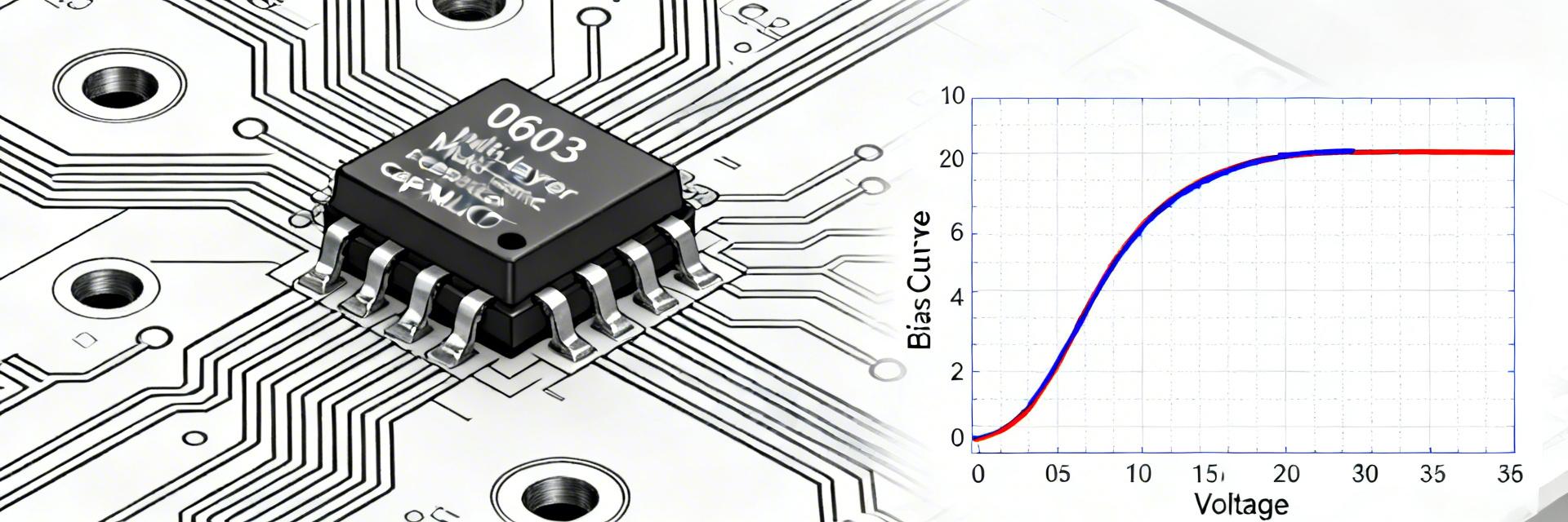
Point: X7R ceramics exhibit measurable capacitance reduction under DC bias. Evidence: Datasheet curves show substantial drops as voltage approaches the 100V limit.
| Bias (V) | Typical C (% of 0V) | Effective Capacitance |
|---|---|---|
| 0V | 100% | 10.0 nF |
| 25V | 85–95% | ~9.0 nF |
| 50V | 70–85% | ~7.7 nF |
| 100V | 40–75% | ~5.5 nF |
Typical Decoupling Placement
Hand-drawn sketch, not a precise schematic / 手绘示意,非精确原理图
3 — Performance Metrics & Reliability Data
Point: Dissipation factor and leakage determine power efficiency and circuit isolation. Evidence: X7R 0603 parts typically maintain DF ≤1.5% under standard 1 kHz tests. Explanation: High insulation resistance (GΩ range) ensures this part remains suitable for battery-powered or high-impedance sensing circuits.
5 — Assembly & Failure Prevention
5.1 — Reflow Profile Guidance
| Reflow Step | Optimal Setting |
|---|---|
| Peak Temp | 245–260°C |
| Soak Duration | 60–120 s |
⚠️ Pro-Tip: To avoid Tombstoning, ensure pad dimensions are symmetrical and avoid using oversized traces directly connected to one pad without thermal relief.
6 — Incoming QA Checklist
- ✅ Capacitance: Verify 10nF ±10% at 1 kHz, 1.0 Vrms.
- ✅ Insulation: Confirm >10 GΩ or 100 MΩ·µF at 100V DC.
- ✅ Visual: Inspect for termination oxidation or micro-cracks via 20x microscope.
- ✅ Solderability: Verify 95% minimum coverage per J-STD-002.
Summary
- Confirm physical footprint and pad pattern for 0603 parts to minimize mechanical stress; verify dimensions in both metric and imperial units.
- Measure capacitance vs. DC bias—expect X7R 100V parts to lose significant capacitance at high field; incorporate bias curves into sizing.
- Set acceptance thresholds for DF and leakage during incoming inspection and maintain a documented sampling plan.
Final Action: Follow the supplied incoming-test checklist before committing the 06031C103K4T2A to high-volume production.
FAQ
How does DC bias affect the capacitance of MLCC 0603 10nF parts?
DC bias reduces effective capacitance in X7R dielectrics; typical 0603 10 nF parts can drop substantially near full rated field. Always measure C vs. bias for the specific lot.
What are the quickest diagnostics for suspected MLCC board failures?
Start with optical inspection for cracks, then use X-ray for hidden internal fractures, and follow with LCR/leakage testing at rated voltage.

