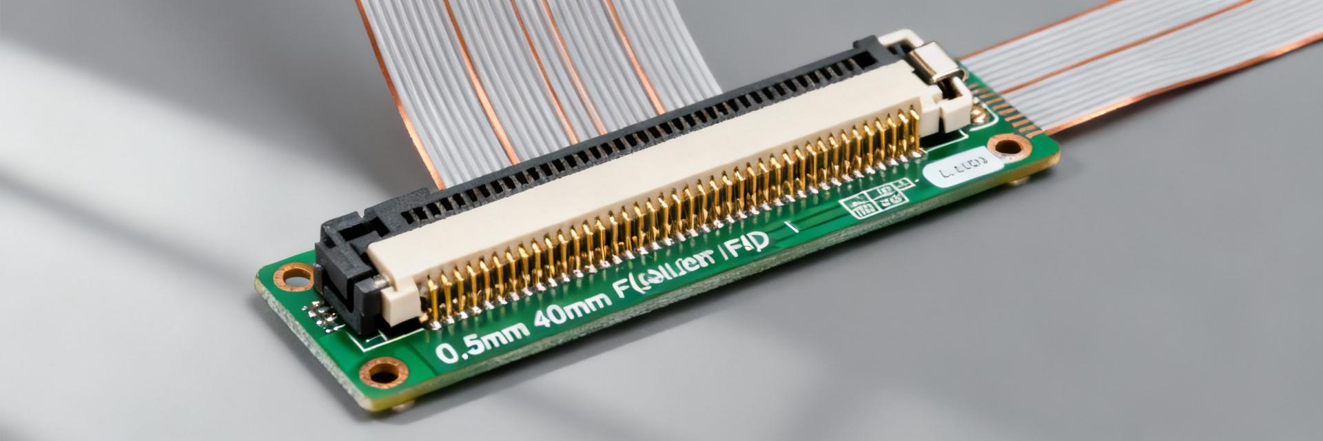
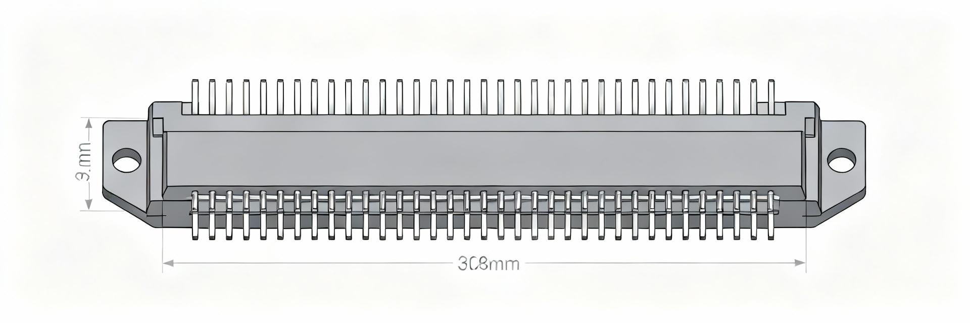
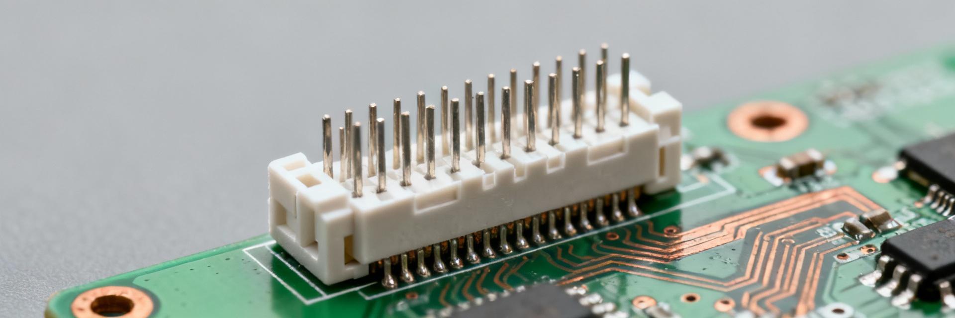
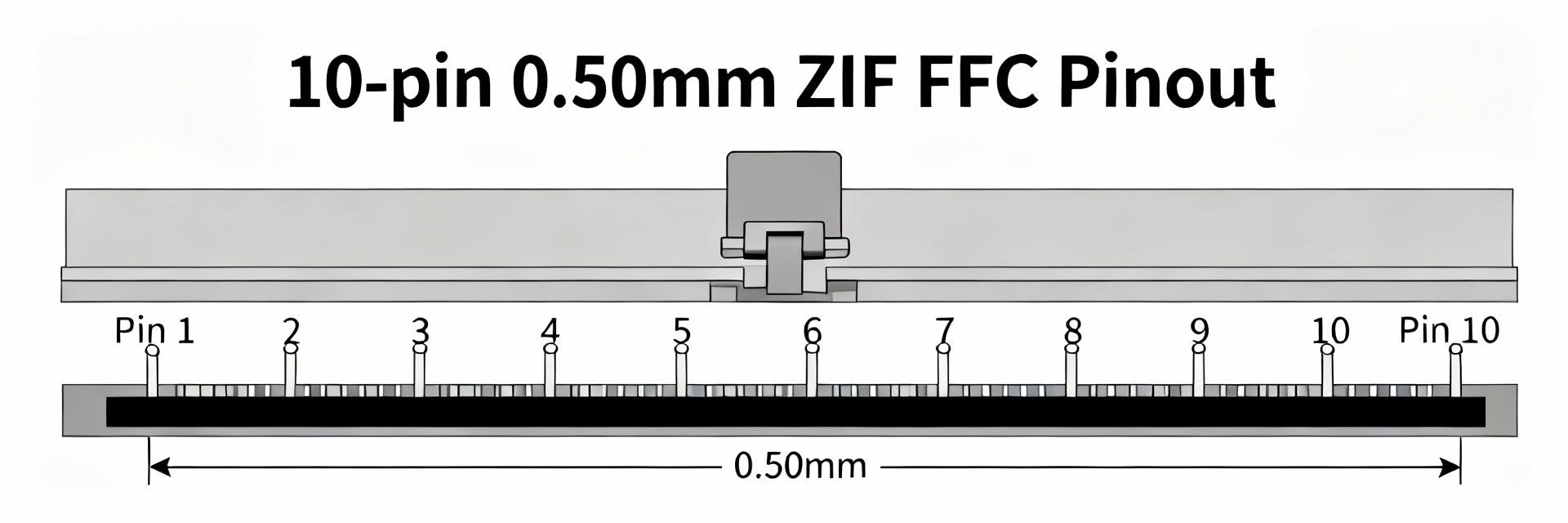
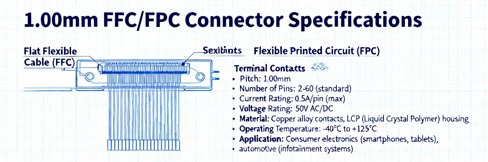
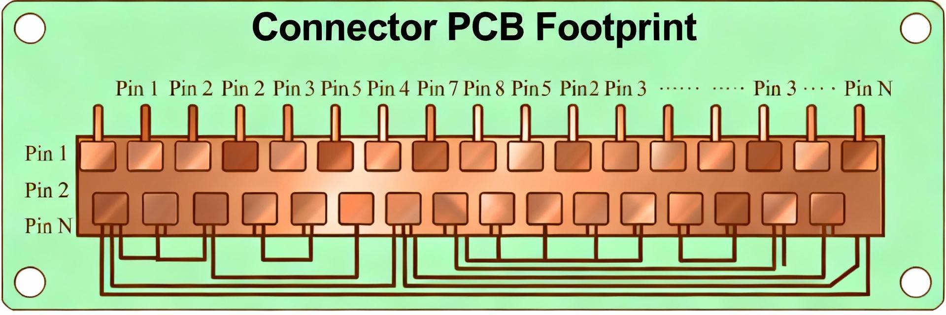
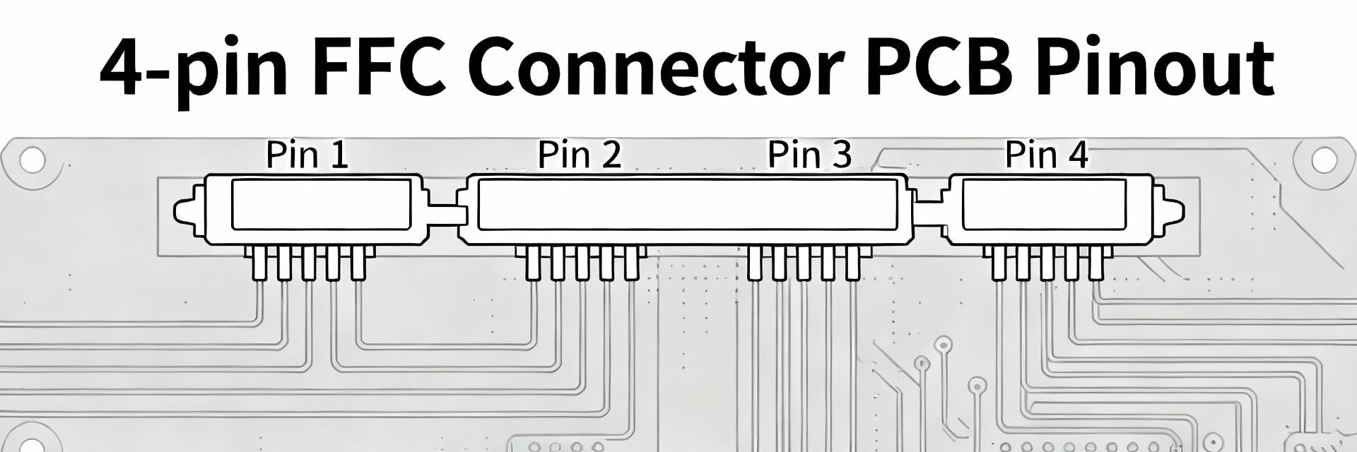
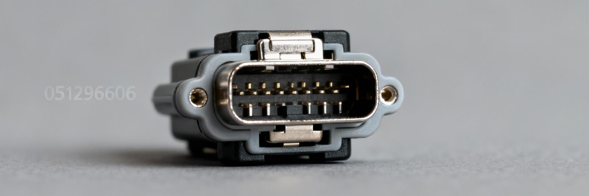
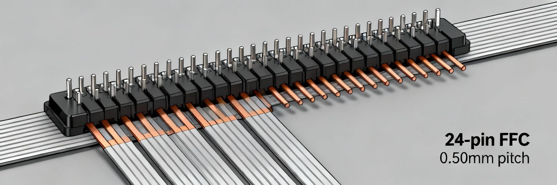
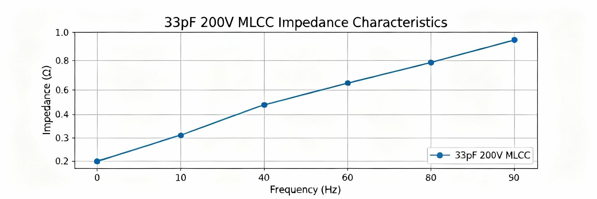
A comprehensive technical guide for designers evaluating high-density flat-flexible connectors. Point Small-pitch flat-flexible connectors account for a large share of interconnect field failures when mechanical and electrical specs are mismatched. Evidence: Field reports show stress, misrouting, and wrong thickness selection are common root causes. Explanation: Methodical review reduces rework and field returns. Insight This guide distills the practical data designers need to evaluate the 0541324062 and equivalent FFCs. Evidence: Mechanical, electrical, footprint, and application-fit guidance. Explanation: Verify compatibility to prevent late-stage surprises. Background: What is the 0541324062 FFC and when to pick it Core identity & key attributes to note Point: The 0541324062 is a 40-position, 0.5 mm-pitch FFC/FPC style connector intended for right-angle surface-mount installations with bottom contacts. Evidence: Part families match this description for ribbon insertion from the mating plane. Explanation: Check pitch (0.5 mm), position count (40P), and mounting style before footprint work. 📌 Suggested diagram: Connector face (front), ribbon insertion direction arrow, and side profile showing the right-angle orientation. Typical product family uses and target applications Point: FFC 0.5mm connectors are favored where routing density and compact mating length are required. Evidence: Common targets include TFT/OLED displays, camera modules, and handheld controls. Explanation: 40P specs map well to short parallel buses where signal count and small pitch balance routing. Data Deep-Dive: Complete mechanical specs at a glance Dimensional & footprint essentials Point: Key numeric checks prevent footprint errors. Evidence: Nominal values: pitch 0.50 mm (0.020"), 40 positions, 0.30 mm FFC thickness, height ≈ 2.00 mm. Explanation: Use the table below for land pattern notes. Dimension Nominal Tolerance Unit Land Pattern Notes Pitch 0.50 ±0.05 mm Stagger keepouts for solder fillet Positions 40 — Pins Verify pad count and pad length FFC thickness 0.30 ±0.05 mm Specify thickness in assembly docs Height above PCB ≈2.00 ±0.10 mm Allow 2 mm clearance for right-angle mate Materials, flammability & compliance tags Point: Housing compound and plating determine service environment. Evidence: Typical housings are thermoplastic (UL 94 V-0) with nickel and gold flash plating. Explanation: Confirm flammability for end-product class and gold thickness for low resistance. Data Deep-Dive: Electrical & performance specs Voltage, current, contact resistance, operating temperature Point: Electrical limits bound safe use. Evidence: Datasheet values: ≤50 V, ≈0.5 A/contact, Explanation: These set design limits for power traces and thermal derating. Max Voltage (50V)100% Limit Current per Contact (0.5A)Recommended Max Reliability metrics & lifetime Point: Mechanical life and retention matter for serviceability. Evidence: Small FFC connectors specify low hundreds of mating cycles; retention forces are defined per spec. Explanation: Plan tests for mating cycles, durability, and vibration. How-to / Design Guide: PCB footprint, assembly & soldering best practices PCB footprint and mechanical anchoring Point: Small pads require precise land patterns. Evidence: Solder mask-defined pads, controlled sizes, and mechanical anchors are recommended. Explanation: Check pad XY size, mask openings, and 2 mm clearance. Reflow, soldering and pick-and-place notes Point: Reliability depends on profile control. Evidence: Use Pb-free reflow, 30–60% stencil aperture, and set fiducials. Explanation: Mitigate bridging and tombstoning by balanced pad geometry. Comparisons & use-cases: 0541324062 vs alternatives Criteria 0.5 mm 40P (this class) Alternate (vertical/1.0 mm) Pitch0.5 mm1.0 mm Positions4040 (or scaled) MountingRight-angle SMDVertical through-hole or SMD HeightLow (~2.0 mm)Taller (varies) FFC thickness~0.30 mm0.2–0.5 mm options Example application scenarios • Small LCD interface: 40P and 0.5 mm pitch fits parallel RGB or MIPI signals with minimal board real estate. • Camera module cable: Dense signals, short run; verify controlled impedance if high-speed lines are used. • Compact sensor array: Multiple channels in a single ribbon; reduces footprint but requires careful routing. Actionable checklist: Sourcing, verification & production QA Pre-order checklist for engineers ▾ Verify exact part number and cross-reference the dimensional drawing; confirm pitch, positions, and mounting orientation. Confirm mating cable thickness and plating; request ESD-safe reels for pick-and-place. Request datasheet pages for mechanical drawings and recommended land pattern before ordering. Prototype test plan & mass-production sign-off ▾ Proto tests: Continuity verification, 50–100 mating cycles, vibration per product class, and thermal cycling. Pass criteria: All contacts within resistance spec, no intermittent opens, no solder joint cracking. Sign-off flow: Prototype → Pilot run with first-article inspection → Production ramp with sampling QA. Summary The 0541324062 is a right-angle, surface-mount, 40-position, 0.5 mm-pitch FFC connector best used where low-profile signal arrays are required. Key checks include mechanical dimensions, electrical limits (≤50 V, ≈0.5 A), and material ratings; prototype mating cycles early. Verify the exact drawing against your footprint, validate reflow profile, and run proto tests to ensure field performance.
2026-01-28 10:27:10