Engineers and technicians often lose hours hunting an unknown part or location on a PCB when all they have is a cryptic code. This guide delivers a clear, repeatable tracing workflow that helps locate, identify, and verify an element quickly and safely.
Purpose & Scope
This document walks through workspace setup, tool prioritization, failure triage, and a stepwise electrical-to-component tracing method for assembly codes like 05-0092-0008.
Key Objective
Establish a real-world tracing example and final actions to confirm and record findings for future identification and repair efficiency.
Background: What "05-0092-0008" denotes on a PCB
Code context and common naming conventions
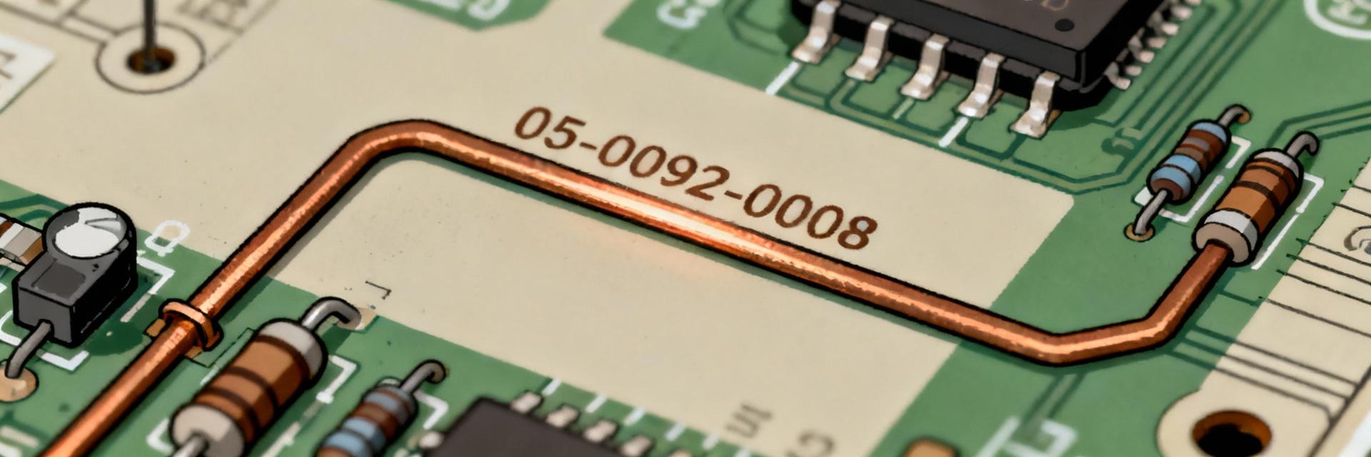
Point: A string like 05-0092-0008 most often appears as an internal part ID, assembly code, or BOM reference printed on silkscreen or a sticker.
Evidence: PCB manufacturers and assemblers typically use hyphenated numeric codes to link board locations to assembly drawings or sub-assemblies.
Explanation: When you see such a code, treat it as an index into documentation or an internal catalog; its presence near a connector, module, or cage often indicates a replaceable assembly rather than a single passive.
Why correct identification matters
Point: Misidentification can cause misrepair, safety hazards, or unnecessary procurement costs.
Evidence: Replacing the wrong regulator or mislabeling a ground net can create thermal or electrical failures.
Explanation: A repeatable identification method reduces downtime by ensuring technicians replace the correct item, preserve warranties, and avoid cascading faults; it also improves traceability for quality analysis.
Tools, workspace, and safety checklist before tracing
Essential tools and test equipment
- ✔ Multimeter & Continuity Probe: Narrow down nets quickly.
- ✔ Microscope/Magnifying Loupe: Reveal hairline cracks and codes.
- ✔ Thermal Camera: Detect live heat signatures.
- ✔ Logic Probe/Oscilloscope: Analyze digital and IC behavior.
Safety and Setup Protocols
Before touching the board, photograph both sides, note board ID, and implement ESD precautions. Photographs capture silkscreen, component orientation, and pre-test conditions.
Common failure modes & diagnostic signs (Triage Data)
| Diagnostic Cue | Likely Failure Mode | Detection Tool |
|---|---|---|
| Burn marks / Discoloration | Overloaded regulator or short circuit | Visual / Microscope |
| High temperature localized spot | Shunted capacitor / Internal IC fault | Thermal Camera / IR |
| Zero voltage on supply rails | Open fuse or blown main switcher | Multimeter (DC Volts) |
| Intermittent data signals | Cold solder joint / Cracked trace | Continuity / Logic Probe |
Diagnostic Efficiency by Method (%)
Step-by-step tracing procedure for 05-0092-0008
Documentation & Markings
Gather silkscreen codes and nearby reference designators (R, C, U, L). Matching footprints and connector types helps infer likely roles.
Top-Down Electrical Approach
Trace from rails to nets. Verifying main rails first reduces search space. Follow continuity along nets toward the suspected module.
Component Verification
Identify package shapes. If marking is ambiguous, lift one leg for accurate measurement. Use oscilloscope for dynamic IC behavior.
Logging & Labeling
Document findings with annotated photos. Reproduce the failure after replacement to ensure the identification loop is complete.
Case Study: Tracing 05-0092-0008 on a Sample Board
Scenario & Symptoms
A unit powers on but the audio output sub-system is dead. Silkscreen near the audio connector shows a code matching an internal assembly reference.
- Rail voltages: Present
- Audio rail: Slightly low
- Local IC: Running abnormally warm
Tracing Walkthrough
The team traced continuity from the audio jack pin to an LDO package. Thermal imaging confirmed abnormal heat dissipation in that specific zone.
Result: Desoldering confirmed the device markings matched the 05-0092-0008 assembly index. Repair time:
Action Checklist & Prevention
Final Checklist
Prevention Strategies
Enhance silkscreen clarity and maintain a parts database. Teams that use QR tags or reference cards reduce future troubleshooting time by up to 40%.
Summary
- • Start with safe prep and clear photos to anchor the identification process for any PCB location and code.
- • Prioritize tools: multimeter and continuity probe first, thermal imaging and oscilloscope as required.
- • Use a top-down electrical trace: confirm rails, isolate nets, then verify at the component level.
- • Document and label findings to prevent repeat searches and to feed a searchable parts database.
