Quick Overview: What the 0501015.WR Is and Where It Fits
Snapshot of Key Ratings
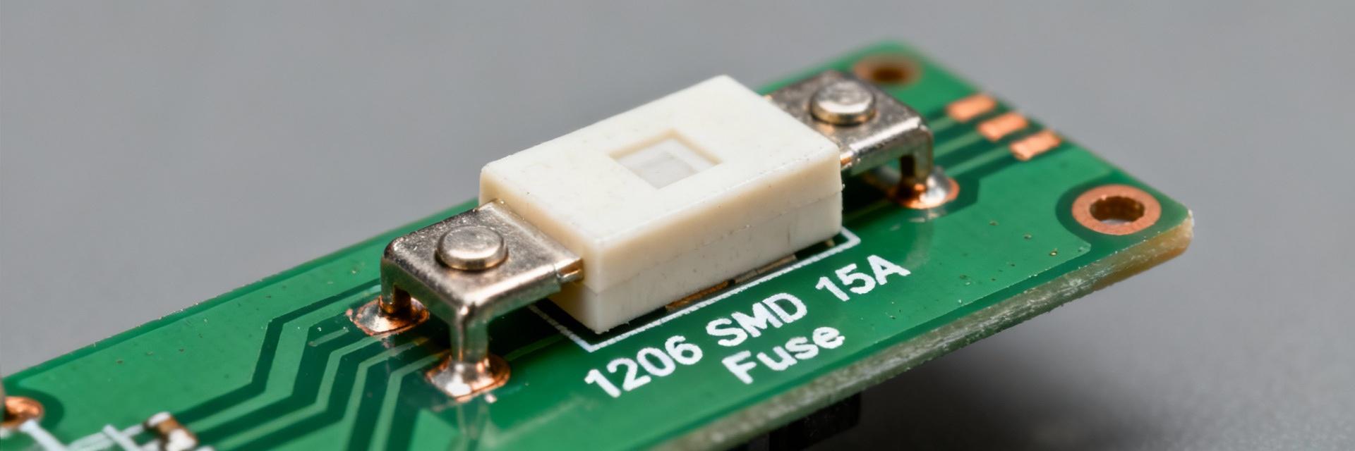
Core datasheet specs establish safe operating envelopes. The part is a 1206 SMD fast/quick-blow fuse rated 15 A continuous and 32 VDC maximum. Its interrupt rating of 150 A at 32 VDC and ceramic body construction define its thermal mass and soldering behavior.
Typical Applications
Typical applications include board-level overcurrent protection for VRMs, DC–DC converters, and low-voltage battery rails. Designers choose this part when space and fast interruption for short-duration faults outweigh the need for time-delay behavior.
Datasheet Deep-Dive: Electrical & Mechanical Specs
Electrical Specifications
Electrical specs dictate loss, thermal rise, and fault-handling. The DC cold resistance of ≈0.0025 Ω implies I·R losses of approximately 0.056 W at 15 A. Always verify your fault current and available let-through energy against the fuse’s I²t to ensure safe interruption without board damage.
| Parameter | Value | Visual Reference |
|---|---|---|
| Continuous Current | 15 A | |
| Voltage Rating | 32 VDC | |
| Interrupt Rating | 150 A @ 32 VDC | |
| DC Cold Resistance | ≈0.0025 Ω | Ultra-Low Impedance |
| Operating Temp | −55°C to +150°C | Extended Industrial Range |
Mechanical & Thermal Specifications
Mechanical and thermal specs constrain assembly. Using the 1206 footprint, the ceramic body provides thermal stability but is brittle. Observe pick-and-place force limits and reflow peak temperatures to avoid microfractures.
Performance Limits & Test Data
Time-Current Curves & I²t
Time–current curves are the primary design tool. To check an inrush profile, plot peak and duration onto the curve: if the inrush current lies left of the hold curve, the fuse will blow. Use datasheet points to compute required I²t for worst-case faults.
Recommended Lab Tests
- DC cold resistance measurement
- Continuity at rated current over time
- Interrupt test at rated voltage
- Thermal cycling & solder reflow tolerance
Design & Application Guidelines
PCB Layout & Thermal Mass
Minimize large copper areas touching pads unless cooling is intended. Excess thermal mass lowers fuse temperature rise but can change blowing behavior. Define keepout areas for high-fault arcs.
Derating & Environment
Apply temperature-derating curves for ambient conditions above 25°C. Consider altitude and enclosure ventilation—mounting orientation can alter convection cooling significantly.
Troubleshooting & Actionable Checklist
Common Failure Modes
Failures usually stem from overcurrent, thermal stress, or assembly damage. Stepwise troubleshooting: measure DC resistance, inspect solder fillets, and review reflow logs before replicating faults on a bench with controlled current.
Selection Checklist for Safe Replacement
- ✔ Match 1206 footprint
- ✔ Continuous current (15 A)
- ✔ Voltage rating (32 VDC)
- ✔ Interrupt rating (≥150 A)
- ✔ Fast-blow characteristic
- ✔ DC Resistance & I²t values
Summary
The 0501015.WR is a high-performance 1206, 15 A fast-acting SMD fuse with a 32 VDC rating and ~150 A interrupt capability. Reading its time–current curves, verifying I²t against your fault energy, and applying datasheet derating rules are essential to avoid misapplication. Use the provided checklist and bench tests to confirm behavior in your specific board context.
Key Takeaways
- Validate DC resistance (~0.0025 Ω) to estimate thermal heating.
- Annotate time–current curves with expected inrush current.
- Thermal mass and nearby copper significantly shift effective derating.
