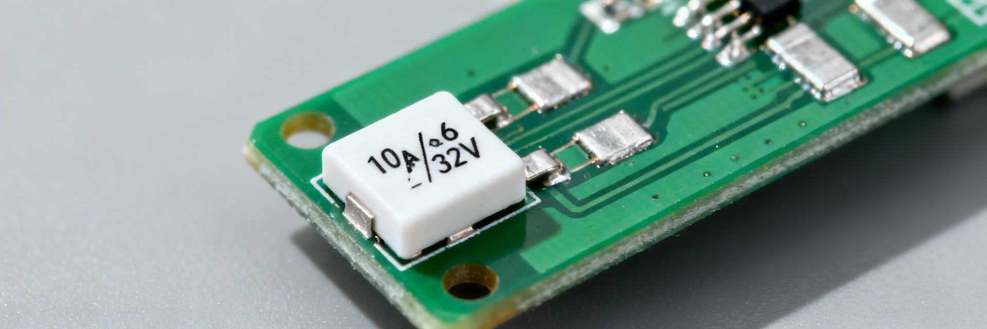
The 0501010.WRA is a 1206-format SMD fuse rated for 10 A, featuring a 32 VDC maximum voltage and high interrupt capability. This engineer-focused guide breaks down critical electrical ratings, thermal considerations, and PCB design best practices for robust board-level protection.
Overview & Package Information
Form Factor and Footprint (1206 / 3216 Metric)
The component utilizes a 1206 (3216 metric) thin-film chip fuse package. For optimal performance, recommended solder-pad geometry should support reliable fillets and thermal transfer:
Environmental & Compliance Notes
Supplied in a lead-free finish, this device meets RoHS and halogen-free requirements. Engineers must strictly follow the reflow guidance regarding peak temperatures to prevent performance shifts during assembly.
Electrical Ratings & Datasheet Breakdown
Rated Current, Voltage & Type
As a fast-acting chip fuse, the 0501010.WRA provides rapid clearing of overloads with minimal energy let-through. This is critical for protecting sensitive semiconductors, though it offers less tolerance for high inrush currents compared to time-delay variants.
Interrupting Capacity
The breaking capacity defines the maximum fault current the fuse can safely clear without catastrophic physical failure (e.g., arcing or package rupture).
Performance Characteristics: Time-Current & Reliability
1 Time-Current Curves
The time-current curve for this SMD fuse features a "steep knee." While small overcurrents (10–20%) might take seconds to open, massive faults clear in milliseconds. Engineers must profile inrush currents to ensure they don't cross the trip threshold during power-up cycles.
2 Thermal Derating
Heating transfers directly into the PCB copper. If operating in environments above 25°C, apply standard derating (typically 0.5% per °C rise). Ensure adequate copper planes are available to act as heatsinks for the 1206 pads.
PCB Design, Placement & Assembly Guidance
Assembly Best Practices
- ✔ Use balanced land patterns to prevent tombstoning during reflow.
- ✔ Align pick-and-place orientation with fiducials for automated visual inspection (AOI).
- ✔ Minimize peak reflow time to avoid internal thermal stress on the thin-film element.
Validation Steps
Perform controlled overcurrent trip verification and use thermal imaging to confirm board-level dissipation. Document test fixtures and safety procedures to capture lot-to-lot variation before full production release.
Engineer's Selection Checklist
Headroom Check
Ensure fuse rating is 125–150% of steady-state current.
Voltage Margin
Verify 32 VDC exceeds max system transients.
Interrupt Rating
Confirm breaking capacity exceeds prospective fault current.
Environment
Account for ambient temperature derating factors.
Summary
The 0501010.WRA is a robust 10 A, 1206-format fast-acting SMD fuse. It is exceptionally suited for board-level overcurrent protection in power distribution, battery systems, and downstream IC guarding, provided that correct derating and PCB thermal practices are applied.
- 1206 Form Factor: Compact 3216 metric footprint for high-density layouts.
- High Interrupt: Capable of clearing fault currents in the 150-300A range.
- Safety: Fast-acting response minimizes let-through energy to sensitive components.
