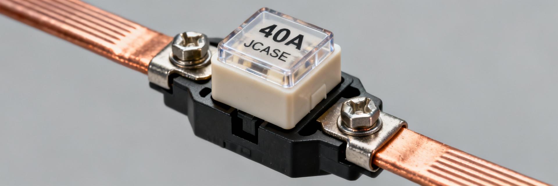
The 0495040.ZXA part is specified for 40 A nominal current, a 32 VDC system voltage rating, and approximately 1,000 A interrupting capacity. This breakdown provides actionable guidance for designers working on high-current vehicle and battery-fed circuits.
This article focuses on the electrical and mechanical data engineers need for reliable protection: steady-state vs. inrush handling, interrupting capability implications, mounting considerations for a cartridge-style slow-blow device, and a concise selection and test checklist referencing official datasheet values and standard bench verification steps.
Background & Quick Reference
At-a-glance Spec Summary
| Parameter | Value (Datasheet) |
|---|---|
| Nominal Current | 40 A |
| Voltage Rating | 32 VDC |
| Interrupting Rating | ~1000 A @ 32 VDC |
| Response Type | Time-delay (slow-blow) |
| Operating Range | Automotive ambient range |
| Form Factor | Cartridge / JCASE-style |
The table above consolidates official values to support rapid decision-making in high-current automotive contexts.
Who should use this part
This cartridge-style, time-delay fuse is intended for high-current vehicle buses, auxiliary power feeds, and loads that present significant inrush (motors, solenoids, capacitive inputs). Use the part where cartridge fuse specs require a slow-blow device to tolerate short inrush pulses while protecting against sustained overloads. Confirm holder compatibility for cartridge installation and the required interrupting capability for the system’s prospective fault currents.
Electrical Ratings Deep-Dive
Continuous and Rated Current Explanation
The 40 A nominal rating denotes the fuse’s intended continuous current at specified ambient conditions; continuous loads should remain below this value after applying derating for elevated ambient temperature, multiple adjacent power conductors, or limited airflow. For steady-state thermal budgeting, apply published derating factors—if the steady-state load approaches 80–90% of rating under worst-case ambient, choose the next higher capacity.
Voltage and Interrupting Capability
The 32 VDC voltage rating defines safe operation within common vehicle electrical systems; the interrupting rating (~1000 A at 32 VDC) indicates the maximum fault current the fuse is certified to safely clear. Designers must compare prospective system fault currents to this interrupting capability to avoid catastrophic failure.
Time-Current Characteristics & Response Behavior
Time–Current Curve and Slow–Blow Behavior
Time-delay (slow-blow) fuses are characterized by a time–current (T–I) curve showing survival of short-duration current peaks. Read the T–I curve by finding the steady-state current on the horizontal axis and observing the clearing time on the vertical axis. This balances inrush tolerance with protection speed for persistent faults.
Testing & Interrupt Tests
Interrupt tests in the datasheet are performed at rated voltage and defined test waveforms. In practice, bench verification uses a controlled short-circuit source to confirm clearing behavior. Always perform representative bench tests in a safe lab setup to validate expectations before field deployment.
Mechanical Form Factor & Environmental Specifications
JCASE Form Factor
The part uses a JCASE-style cartridge intended for matching holders. Confirm mechanical mating with specified holders and ensure mounting allows proper ventilation. Use official dimensional outlines to verify clearance and terminal access.
Thermal Limits
Operating and storage temperature limits are critical. Thermal derating with elevated ambient can reduce capability; plan with conservative margins and schedule periodic inspections where ambient exceeds recommended values.
Typical Applications & Case Study
Common Scenarios: Main vehicle power distribution, motor/solenoid protection, auxiliary power circuits, and battery-fed subsystems (12–32 V).
In-Field Example: For a 30 A DC motor with a 4× inrush factor:
- 1 Selection: Choose 40 A slow-blow to tolerate ~120 A inrush.
- 2 Verification: Check fault current vs 1000 A interrupting rating.
- 3 Implementation: Torque terminals and perform bench tests.
Selection, Testing & Installation Checklist
Pre-selection Checklist
- ✓ Confirm system voltage ≤ 32 VDC.
- ✓ Determine inrush multiplier vs steady-state.
- ✓ Compare fault current to 1000 A rating.
- ✓ Account for ambient temperature derating.
Post-installation & Maintenance
- → Bench-test continuity before full deployment.
- → Inspect holder seating for discoloration.
- → Investigate root cause for repeated blows.
Summary
- 0495040.ZXA: 40A / 32VDC / 1000A Interrupt capacity—suitable for high-current automotive systems.
- JCASE Cartridge: Time-delay characteristics tolerate short inrush while protecting against overloads.
- Strategy: Weigh steady-state, inrush, and thermal derating; complete with bench verification.
Frequently Asked Questions (FAQ)
How do I confirm the 0495040.ZXA datasheet ratings apply to my 12 V system? +
Compare system voltage and worst-case fault current to the datasheet. For 12 V systems, the 32 VDC rating provides a safe margin. Ensure prospective peak fault current stays below 1000 A and apply ambient derating for continuous current.
Can I use the same cartridge fuse for motors with frequent start cycles? +
Yes, provided the slow-blow rating tolerates the repeated inrush without cumulative heating exceeding thermal limits. Use the T–I curve and duty cycle analysis to confirm acceptable behavior under repeated starts.
What are quick signs of improper installation for this cartridge fuse? +
Poor seating, discoloration at terminals, unusual heating under normal load, or frequent nuisance opens are red flags. Verify holder compatibility and contact torque before increasing the fuse rating.
