The key numbers engineers search first are: 32 VDC voltage rating, 20 A nominal current, a 1,000 A interrupting rating at 32 VDC, maximum recommended ambient +125 °C, and a time-delay (slow-blow) characteristic. These headline values define system suitability, surge tolerance, and protective coordination.
Background & Product Overview
What this part is and where it's used
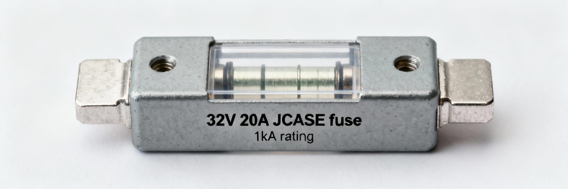
This part is a cartridge-style, JCASE-group fuse intended for high-current DC protection in automotive and heavy harness applications. The form factor requires a dedicated holder and is optimized for panel or inline harness mounts.
The slow-blow time-delay behavior permits controlled inrush for motors and capacitive loads while protecting against sustained overloads. This makes it ideal for starter motors, traction circuits, and auxiliary high-current feeds. Ensure the 0495020.ZXA fuse is included in early BOM reviews for holder compatibility.
Quick-specs at a glance
| Parameter | Value |
|---|---|
| Voltage Rating | 32 VDC |
| Current Rating | 20 A (nominal) |
| Interrupting Rating | 1,000 A @ 32 VDC |
| Response | Time-delay (slow-blow) |
| Max Ambient | +125 °C |
| Group / Size | JCASE 495 / cartridge |
Complete Electrical Specifications
Current, voltage and interrupting ratings
Nominal current, voltage rating, and interrupting capability define the safe operating envelope. Designers must derate continuous current for elevated ambient and enclosure conditions (typical practice: allow 75–85% of rating in confined spaces). Ensure the interrupting rating exceeds the maximum prospective fault current at the fuse location to prevent catastrophic failure.
Time–current behavior & thermal characteristics
Slow-blow construction yields longer trip times near modest overloads. Elevated ambient temperatures (+125 °C max) shorten the fuse life and accelerate aging. Always apply thermal derating and verify trip points under representative mounting conditions during validation.
Mechanical, Environmental & Compliance Ratings
Physical & Mounting
Cartridge/JCASE size defines geometry. Verify dimensional drawings in ECAD reviews. Inspect terminal surfaces for corrosion protection and ensure visual blow indication access.
Environmental Limits
Confirm storage ranges, vibration, and shock ratings. Include IP sealing notes if the fuse is in exposed or under-hood locations per automotive standards.
How to Read the Datasheet & Select Equivalents
Matching Parameters
- Match or exceed voltage rating
- Choose equivalent time-delay
- Apply thermal derating rules
ECAD Verification
Use ECAD models to verify clearance, creepage, and mounting tolerances. Double-check terminal geometry to ensure low contact resistance and predictable thermal behavior.
Installation & Troubleshooting Checklist
Pre-installation: Verify rated values, perform visual inspection, ensure holder cleanliness, and check ambient conditions. Run controlled overcurrent tests if possible.
Common Failures: Diagnosed by measuring steady-state load current, checking for intermittent shorts, and inspecting holder contact resistance. Replace only with correct time-delay rated parts.
Final Review Key Summary
- Core Parameters: Ensure 32 VDC, 20 A continuous, and 1,000 A interrupting capacity match system fault levels.
- Thermal Limits: Use the slow-blow curve and apply ambient derating for hot installations.
- Mechanical Fit: Validate footprint and holder compatibility via ECAD models before production.
