Recent lab benchmarks show a clear shift toward higher-density board-to-cable interconnects: adoption of 0.5mm pitch FPC connectors in portable electronics has risen notably, driven by slimmer form factors and higher pin counts. In controlled tests, common failure modes include intermittent contact from inadequate retention, solder joint cracking under thermal cycling, and increased insertion loss at high data rates. Supply-chain pressure points center on lead-time volatility and limited vetted sources for low-profile variants.
The purpose of this article is to present reproducible benchmark results, a test protocol tailored to 0.5mm pitch parts, and a practical sourcing playbook to help engineers and buyers select reliable parts quickly. Readers will find background on term definitions, a data deep-dive on electrical and mechanical metrics, a lab test matrix, qualification KPIs, and procurement tactics they can apply immediately to shorten time-to-market.
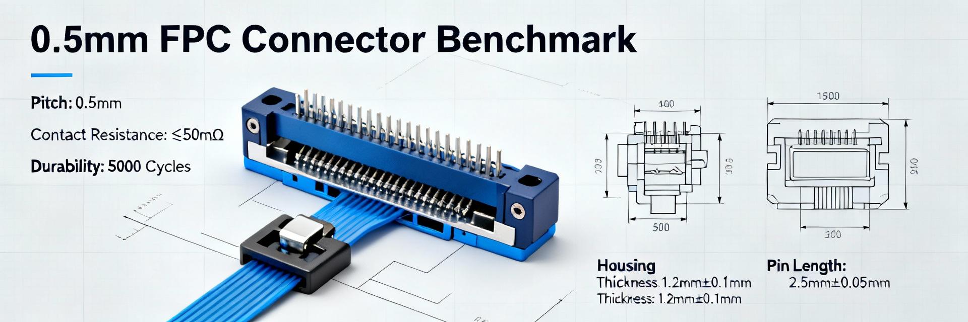
Background: Why 0.5mm FPC Connectors Matter
FPC Connector Basics and Terminology
Point: Clarity on terminology reduces design errors. Evidence: An FPC (flexible printed circuit) differs from FFC (flat flexible cable) by construction and termination style. Explanation: Pitch is center-to-center contact spacing; 0.5mm implies high density that impacts routing and manufacturability. ZIF (zero insertion force) vs non-ZIF governs mating stress, while top/bottom contact and right-angle vs straight define assembly geometry and enclosure fit.
Common Applications & Market Drivers
Point: Miniaturization fuels demand. Evidence: Device segments—wearables, compact displays, IoT sensors, and ultra-thin handhelds—favor 0.5mm for higher pin counts in constrained spaces. Explanation: Design drivers include thinner stacks, tighter routing, and higher signal density; sourcing pressure grows as teams need validated, low-profile parts quickly to meet aggressive product cycles.
Data Deep-Dive: Performance Metrics
Electrical Performance Thresholds
Insight: Recommended tests record contact resistance, insertion loss, crosstalk, and DC continuity. At 0.5mm pitch, conductor proximity complicates impedance control and raises EMI risk.
Mechanical & Reliability Metrics
| Test Parameter | Target Criteria |
|---|---|
| Mating Cycles | |
| Thermal Cycling | No crack propagation |
| Retention Force | Standardized N/pin min. |
Insight: Mechanical resilience predicts field life. Trade-offs emerge—lower profile and smaller actuators often reduce cycle life; quantify retention vs. lifecycle early.
Benchmark Protocol: Lab Evaluation Guide
Recommended Test Matrix
Reproducible fixtures yield actionable comparisons. A minimal matrix includes DC continuity, S-parameter insertion loss, return loss up to target bandwidth, crosstalk, and mechanical rigs for mating/unmating. Use precision alignment fixtures (±0.05mm alignment) and log data at 1 Hz for mechanical cycles.
Interpreting Results & KPIs
Track mean contact resistance and degradation slope. Red Flags: rising contact resistance >20% from baseline, >0.5% failure rate per 100 cycles, or Δimpedance beyond design tolerance (typically ±10%). Translate lab KPIs to product MTBF based on expected user actions.
Sourcing Playbook: Selecting Suppliers
📋 Spec-Sheet Checklist & Qualification
Evidence: Request pitch confirmation, mating style, contact plating material, recommended PCB footprint, terminal type, lifecycle ratings, and RoHS/REACH declarations. Insist on supplier-provided test reports aligned to the benchmark protocol. Explanation: Including these in RFQs reduces back-and-forth and enables objective qualification.
💰 Commercial Considerations & Risk Mitigation
Evidence: Assess lead times, MOQ, and price breaks. Demand forecast accuracy and flexibility influence selection. Explanation: Include RFQ questions on sample availability and dual-sourcing options. Mitigate risk with buffer stock and contractual clauses for late-change penalties.
Design Pitfalls
Small errors produce field failures. Frequent mistakes include incorrect footprint pad sizes, insufficient mechanical retention, and inadequate strain relief. Quick Fix: Validate footprint against supplier land-pattern and route strain relief traces away from flex bend zones.
Procurement Pitfalls
Procurement oversights compound program risk. Errors include accepting incomplete spec sheets and ignoring batch traceability. Mitigation: Authenticate sample requests, demand contractual quality clauses, and plan alternate sources before production buys.
Actionable Checklist for Teams
Technical Review
- ✔ Verify footprint accuracy & mating direction
- ✔ Assess shielding needs & mechanical retention
- ✔ Validate against lifecycle test reports
Procurement Action Plan
- ✔ Structure RFQ with pricing tiers & lead times
- ✔ Engineering sign-off on samples before bulk
- ✔ Establish forecast-driven order cadence
