0.3mm 27-pos FPC Connector: Spec & Solderability Data
High-density interconnects increasingly rely on ultra-fine-pitch FPC receptacles; a 0.3mm 27-pos FPC connector compresses 27 signal paths into a sub-inch footprint, raising sensitivity to coplanarity, pad definition, and thermal stress compared with larger-pitch parts. This article delivers a clear spec breakdown, solderability guidance, recommended reflow profile ranges (verify with connector datasheet), common failure modes, and a practical QA/assembly checklist for reliable production.
The goal is actionable guidance for design and process engineers: list essential mechanical and electrical baseline values, map datasheet fields to test standards, explain solderability risks and conservative Pb‑free reflow ranges, and close with a shop-floor checklist.
Key Specs & Mechanical/Electrical Baseline
Physical Dimensions & Pinout
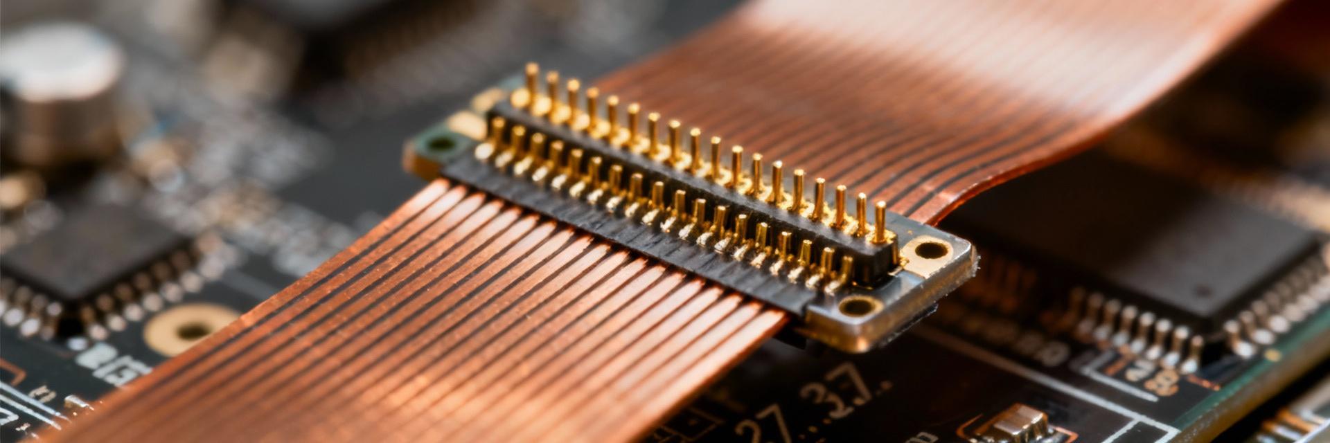
Point: For layout and mechanical integration, designers must capture pitch, position count, overall length, mating orientation, PCB footprint outline, mating force, and retention details. Evidence: A 0.3 mm / 0.012" pitch with 27 positions yields a nominal contact span; overall length and pad array depend on end-margin design (verify with datasheet). Explanation: Check coplanarity tolerance, pad-to-pad clearance, and available solder fillet space; specify fiducials and keepout zones to ensure repeatable placement and insertion alignment.
Electrical Ratings & Materials
Point: Electrical spec fields to record include rated voltage, current per contact, insulation resistance, contact resistance, and plating/materials. Evidence: Typical conservative design values for fine-pitch FPC contacts are ~50 V rated and 0.1–0.5 A per contact depending on contact cross-section (verify with datasheet). Explanation: Plating (Au over Ni vs. other finishes) impacts contact reliability and solderability—gold top-coatings improve contact life but can change wetting behavior.
| Parameter | Typical Range / Note | Visual Indicator |
|---|---|---|
| Pitch | 0.3 mm (0.012") | |
| Positions | 27 | High Density |
| Rated Voltage | ~50 V (Nominal) | |
| Current per Contact | 0.1–0.5 A | |
| Contact Finish | Au over Ni (Gold Plated) | ★ Solderability Grade |
Spec Compliance & Test Standards
Applicable Industry Standards
Point: Map connector spec fields to industry standards for consistent acceptance criteria. Evidence: Use IPC and J‑STD families for solderability and termination assessments. Explanation: Solderability is commonly judged to J‑STD‑002 criteria; mating durability should reference the connector datasheet cycle count.
Interpreting Datasheet Tables
Point: Read datasheet tables with an emphasis on worst-case tolerances and assembly constraints. Evidence: Translate max reflow temperature and allowable warpage into process limits. Explanation: Look for min/max columns, units, and notes. Flag values that require "verify with datasheet" for gating criteria.
Solderability & Recommended Reflow Profile
Solderability Considerations
Solderability depends on terminal plating, oxidation state, and wetting characteristics. Common tests: Wetting evaluation per J‑STD‑002 and AOI/x‑ray acceptance criteria for fillet formation. Quantify acceptable wetting percentage and fillet geometry to reduce ambiguity during production sign-off.
Recommended Reflow Profile (Pb-Free):
Preheat: 150–180°C | Soak: 190–210°C (60–90s)
Peak: 245–255°C | TAL: ~35–50s | Ramp: ~2°C/s
Thermal Profile Visualization
* Time vs. Temperature Curve (Abstract)
Assembly & Stencil Best Practices
- • Stencil Design: Reduction to 60–80% of pad area; use Type 3 or finer paste.
- • Process Controls: Inline AOI and X-ray for hidden joints are mandatory.
Failure Modes & Actions
Critical Risk: Solder bridging and misalignment due to 0.3mm pitch.
Action: Footprint redesign and aperture tuning; prioritize risk-priority concepts during NPI.
Summary & Quick Checklist
Accurate interpretation of connector spec tables and disciplined solderability practices are critical to reliable production. Verify all numeric guidance against the connector datasheet before production release.
