Designers selecting a compact PCB protection device need precise electrical and footprint details to avoid late-stage rework. This guide summarizes the core electrical and mechanical highlights for a 1206-class slow-blow SMD rated for roughly 2.5 A operating current and a 63 V rating, with typical interrupt capability sized for common board-level protection. Accurate specs and a verified land pattern reduce solder joint failures, thermal overstress, and false trips, making the difference between a reliable production run and costly respins.
The article’s purpose is to provide a single-source reference: concise specs, PCB land-pattern guidance, assembly and verification best practices, and a pre-production checklist so designers can validate CAD library footprints and prototype behavior before volume assembly.
Product Background: What 046802.5NRHF is and Where It’s Used
Part Identity & Typical Applications
Point: The device is a 1206 (3216 metric) slow-blow SMD protection element intended for moderate current circuits. Evidence: It is specified for board-level overcurrent protection and inrush-tolerant applications. Explanation: Typical uses include power input filtering, battery and charger protection, motor controllers with start-up surge, and consumer or industrial control PCBs where short transients must not trigger nuisance opens; designers choose slow-blow parts when temporary inrush or capacitive charging is expected and continuous overload must be distinguished from short duration events.
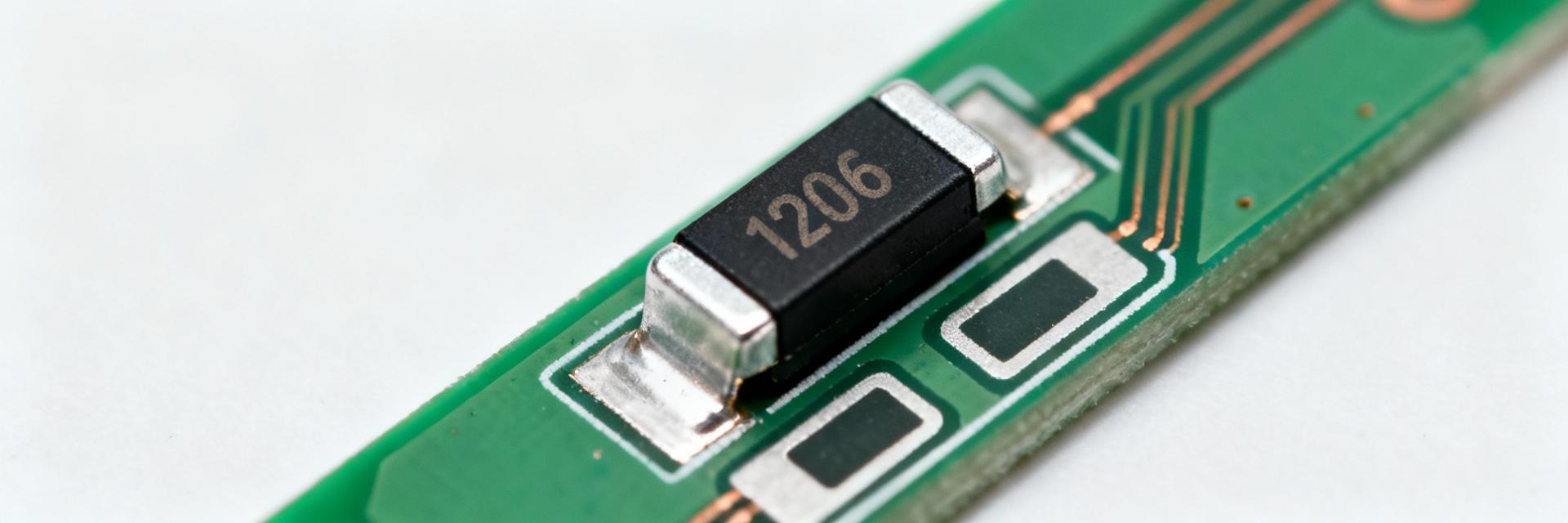
Package & Marking Cues
Point: The component belongs to the 1206 footprint class with compact top marking or no visible mark. Evidence: Physical cues include rectangular ceramic body ~3.2 × 1.6 mm and metalized end caps; reels typically show tape-and-reel orientation consistent with other 1206 passives. Explanation: To confirm part vs. look-alikes, verify package nominal dimensions, end-cap geometry, and cross-check part code fields in the CAD library; visual similarity to resistors/capacitors means footprint metadata and reference designator discipline are essential for correct pick-and-place placement.
Key Electrical and Mechanical Specifications
Electrical Ratings & Time-Current Characteristics
Point: Core electrical ratings determine safe operating envelope and trip behavior. Evidence: Nominal rated current is ~2.5 A with a rated voltage near 63 V (AC/DC), and interrupt ratings sized for board protection levels. Explanation: Interpreting slow-blow (time-delay) curves requires reading the time to open at multiple multiples of rated current; for inrush scenarios, designers check that short pulses at 5–10× rated current do not exceed the time-to-open.
Mechanical, Thermal and Reliability Specs
Point: Mechanical and thermal limits affect layout and life expectancy. Evidence: Package is 1206 with typical soldering compatibility for Pb-free reflow; operating case temperatures and solderability windows are provided on datasheets. Explanation: Designers must follow recommended reflow profiles, observe maximum case and ambient temperatures, and account for MTTF/lifecycle ratings; elevated board temperatures or frequent cycling reduce fuse element life.
Footprint & Land-Pattern Guidance
Recommended PCB Footprint Dimensions
A correct pad geometry ensures reliable solder fillets and mechanical support for the 1206 fuse. Following IPC-class tolerances for 1206 components gives consistent results across assemblies.
| Feature | Recommended (Nominal) |
|---|---|
| Pad length (each) | 1.6 mm |
| Pad width | 1.2 mm |
| Pad-to-pad spacing (gap) | 0.8 mm |
| Solder mask clearance | 0.15 mm |
| Keepout / silkscreen | 1.0 mm around pads |
Solder Paste Note: Proper paste aperture and thickness reduce tombstoning and voiding. Apertures sized to 60–80% of pad area and 0.12–0.15 mm paste thickness are common for 1206 ceramic parts. Ensure balanced paste release to avoid movement during reflow.
PCB Layout & Thermal Considerations
Thermal Management: Trace geometry and copper thickness determine sustained current capacity and temperature rise. Use IPC-2152 calculators to map continuous current to trace width. Add thermal relief if the fuse sits near large copper pours, but avoid excessive thermal sinking that could shift opening characteristics by cooling the element during a fault.
Placement & Assembly: Fuses on edges or near connectors experience bending stresses during handling. Orient the part so solder fillets take the primary mechanical load (long axis parallel to likely flex), and include fiducial alignment zones for accurate pick-and-place placement.
Verification Checklist
- Continuity check (four-wire preferred)
- Measure series resistance (mΩ range)
- Visual inspection of solder fillets
- Controlled current ramp validation
- Verify time-to-open behavior
Quick Reference & Actionable Checklist
| Field | Value (example) |
|---|---|
| Part number | 046802.5NRHF |
| Rated current | ~2.5 A |
| Rated voltage | 63 V |
| Package | 1206 / 3216 Metric |
| Pad geometry | 1.6 × 1.2 mm pads, 0.8 mm gap |
BOM & Procurement: Capture exact part number, package code, time-current class, and footprint version. Lock footprint geometry in the CAD entry and require a datasheet revision field on POs to ensure the correct variant is ordered.
Key Summary
- • Confirm electrical limits and slow-blow behavior to prevent nuisance opens; validate curves against inrush profiles.
- • Use the recommended pad geometry (1.6 × 1.2 mm pads, 0.8 mm gap) to ensure reliable fillets and minimize tombstoning.
- • Account for trace width and copper thickness; derate traces appropriately to maintain continuous current margins.
- • Verify in-circuit resistance and follow the BOM checklist to guarantee footprint compatibility before field replacement.
Summary Overview
Confirm 046802.5NRHF electrical specs and expected slow-blow behavior and apply the recommended 1206 footprint and assembly notes to minimize solder and thermal issues. Designers should capture precise footprint geometry in the CAD library, include required BOM fields, and run prototype verification with time-current tests to validate behavior under expected inrush. Action: verify datasheet curves and footprint dimensions in the CAD library, finalize stencil apertures on prototype runs, and run a quick functional verification pass before authorizing volume assembly.
