Point: The 046801.5NR is a board-level, slow-blow SMD fuse intended for compact power protection.
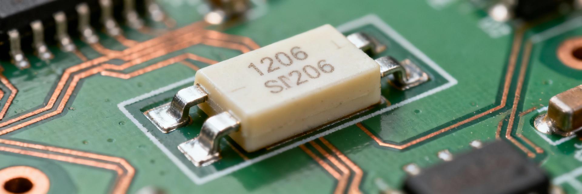
Evidence: It is specified as a 1.5 A nominal slow-blow device in a 1206 (3216 metric) package with a 63 V rating and roughly 50 A breaking capacity.
Explanation: Designers should treat those numbers as the starting constraints when matching protection to in-circuit fault and inrush profiles.
Point: This guide converts datasheet figures into practical limits and validation steps. Evidence: Time-current curves, thermal derating and mechanical mounting data determine real-world behavior. Explanation: Following structured test protocols and PCB thermal practices reduces false trips, avoids overstress from repeated faults and ensures predictable protection margins for board assemblies.
Product Overview & Key Specs
Electrical Ratings at a Glance
Key electrical parameters define allowable operating and fault conditions. The device is rated 1.5 A nominal, 63 V AC/DC maximum, with ~50 A interrupting capacity.
| Parameter | Value (Typical) |
|---|---|
| Nominal Current | 1.5 A |
| Voltage Rating | 63 V AC/DC |
| Interrupting Capacity | ≈50 A |
| Package Size | 1206 (3216 Metric) |
Datasheet Breakdown: Performance Curves & Limits
Time-Current Characteristics
Slow-blow fuses tolerate short overcurrents (inrush). For 1.5 A, transient inrush multiples (3–7× load) may be acceptable if brief; sustained multiples drive the fuse into its trip region.
Inrush Tolerance Capacity (Typical)Thermal Derating
Ambient and soldering temperatures change allowable current. Apply 10–25% margin at elevated temperatures and respect peak reflow constraints.
Operating Reliability MarginTesting & Validation Guide
Bench Testing Protocol
Use a programmable current source and execution step tests (200%, 500%, 1000% of rating). Record blow times and compare them to the datasheet curve to assessments degradation.
PCB Layout Considerations
- Avoid heat sources or large copper planes that alter fuse temperature.
- Ensure consistent solder wetting with optimized pad length.
- Consider mechanical shock protection for high-vibration environments.
Selection Checklist & Replacement
Sizing Rule
Choose 1.5 A slow-blow for 0.8 A steady load with 5× inrush. Validate via I²t curves.
Replacement
Replace only with identical part numbers. Never exceed rated voltage/current.
Quantify
Measure inrush magnitude and duration before board-level integration.
Key Summary
- ✔ 046801.5NR: 1.5 A slow-blow, 63 V rating, ≈50 A interrupting capacity.
- ✔ Test protocol: Perform step tests at 200%, 500% and 1000% with precise time logging.
- ✔ PCB/thermal rules: Design pads to control thermal coupling; derate current for high ambient conditions.
