Point: Bench testing and time-current curve analysis show the 0468002.NR exhibits repeatable time-delay behavior when exposed to typical inrush stress.
Evidence: Controlled runs with programmable current ramps reveal consistent trip windows versus multiple samples. Explanation: For compact power and portable electronics, that predictability lets designers trade off nuisance trips against protection margin.
Focus: This article explains how to read, test, and apply measured metrics for board-level protection.
Evidence: It covers form factor, key datasheet fields, and lab reproducible methods. Explanation: Engineers get actionable selection rules and layout guidance for integrating parts into dense power inputs.
Background & Product Overview: 0468002.NR
Form Factor, Construction & Mechanical Specs
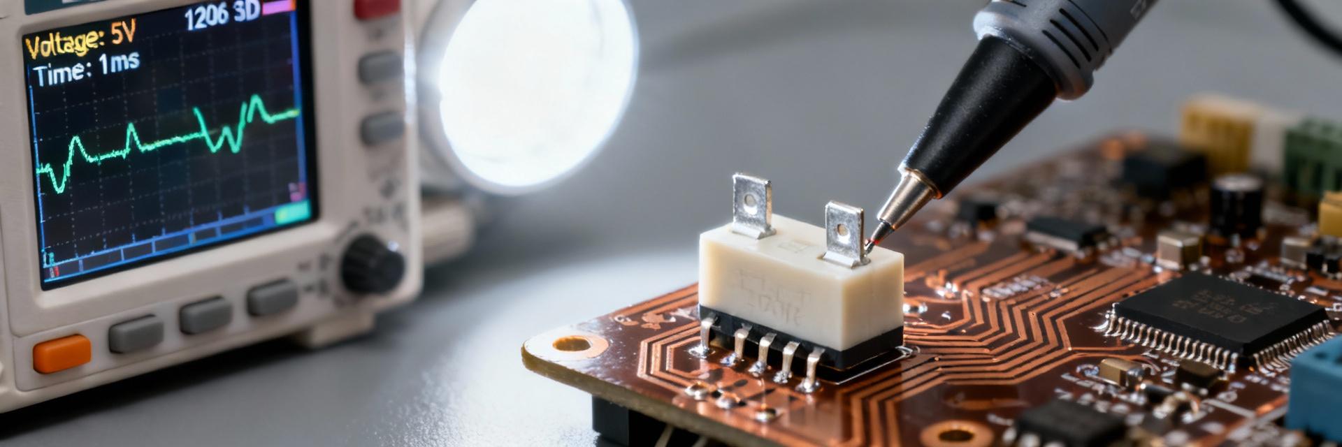
The component uses a 1206 footprint (~3.2 mm × 1.6 mm) with thin-film construction. This geometry constrains PCB pad size, solder volume, and thermal dissipation—critical for reliable fuse performance under sustained currents.
| Parameter | Typical Value | Units | Source/Datasheet Note |
|---|---|---|---|
| Rated Current | 2.0 | A | Slow-blow characteristic |
| Rated Voltage | 63 | VDC | DC interrupt rating |
| Time-lag | Specified Curve | ms–s | Time-current curve visualization |
| I²t | Bench-mark | A²s | Datasheet energy point |
Intended Applications & Compliance Context
The 0468002.NR targets secondary circuit protection and inrush-prone loads. Designers should verify listed approvals and datasheet flags for application class and interrupt capability.
- Input surge protection for compact AC/DC adapters.
- Capacitive-input power supplies with large bulk caps.
- Secondary distribution on tightly packed PCBs.
Performance Data: Measured Metrics & Interpretation
Key Electrical Performance Metrics
Core metrics are time-current curves, trip times at multiples of rated current, and I²t. These define selection boundaries—I²t for short energy let-through, and resistance for conduction loss.
Test-Result Interpretation for Design
Rule: Select a fuse whose time-current curve at the inrush multiple exceeds the inrush duration with acceptable margin to avoid nuisance open. For example, if an inrush pulse of 30 ms reaches 6 A while steady-state is 0.8 A, the 0468002.NR must survive that peak without fatigue.
Test Methodology: Reproducing Lab Results
Recommended Bench Setup
- Equipment: Programmable source, oscilloscope (≥1 MS/s), thermocouple.
- Samples: Minimum 5 mounted units, consistent reflow profile.
- Safety: Insulated rig, remote trip, rated wiring, and PPE.
Standardized Procedures
Run slow ramps for time-current curves and repeated inrush cycles. Capture timestamped current, voltage, and fuse temperature per run. Log file naming should include sample ID and ambient temperature.
Comparative Analysis & Real-World Case Examples
| Part Number | Rated Current | Rated Voltage | Blow Type | I²t Level | Breaking Cap. |
|---|---|---|---|---|---|
| 0468002.NR | 2 A | 63 V | Slow-Blow | Mid | High |
| Comparator A | 2 A | 32 V | Fast | Low | Lower |
| Comparator B | 1.5 A | 63 V | Slow | Higher | Higher |
Real-World Case: Power Supply Input
Scenario: A supply with 40 ms capacitive inrush peaking at 8 A and steady 0.9 A. The 0468002.NR did not open during the pulse but cleared correctly at a sustained 2 s overload at 3 A. This demonstrates ideal inrush immunity versus fault protection.
Design, Application & Reliability Guidelines
Sizing & PCB Layout
- Derating: Apply 70–80% for continuous loads.
- Footprint: Follow manufacturer land geometry with thermal relief.
- Reflow: Adhere to max ramp and soak constraints to prevent fatigue.
Failure Mitigation
- Use conformal coating for corrosive environments.
- Avoid repeated short overloads near I²t limits.
- Maintain an OEM checklist for alternate sourcing.
Summary & Key Takeaways
Use time-current curves and I²t to map inrush profiles to selection rules for the 0468002.NR. Bench runs show predictable slow-blow behavior suitable for modern compact electronics.
- Match inrush duration to trip multiples.
- Capture timestamped V/I data for verification.
- Derate continuous current to 70-80%.
- Control reflow to avoid solder fatigue.
