0466005.NR SMD Fuse Performance Report: 5A 32V Test Results

0466005.NR SMD Fuse Performance Report: 5A 32V Test Results

Independent lab testing shows the thin-film chip cleared 5A steady-state at a 32V system rating and met the defined interrupt and thermal limits under controlled conditions. This headline metric matters because designers rely on predictable clearing and limited thermal rise when protecting low-voltage I/O, battery, and USB-class circuits.

The report covers methods, key electrical results, reliability outcomes, comparisons, and actionable design guidance.

Background: SMD Fuse Basics & Spec Context

0466005.NR SMD Fuse Performance Report: 5A 32V Test Results Visualization

Key specifications to know

Point: Designers must treat nominal current, voltage rating, package size, blow characteristic, interrupt rating, and thermal range as primary selection drivers.

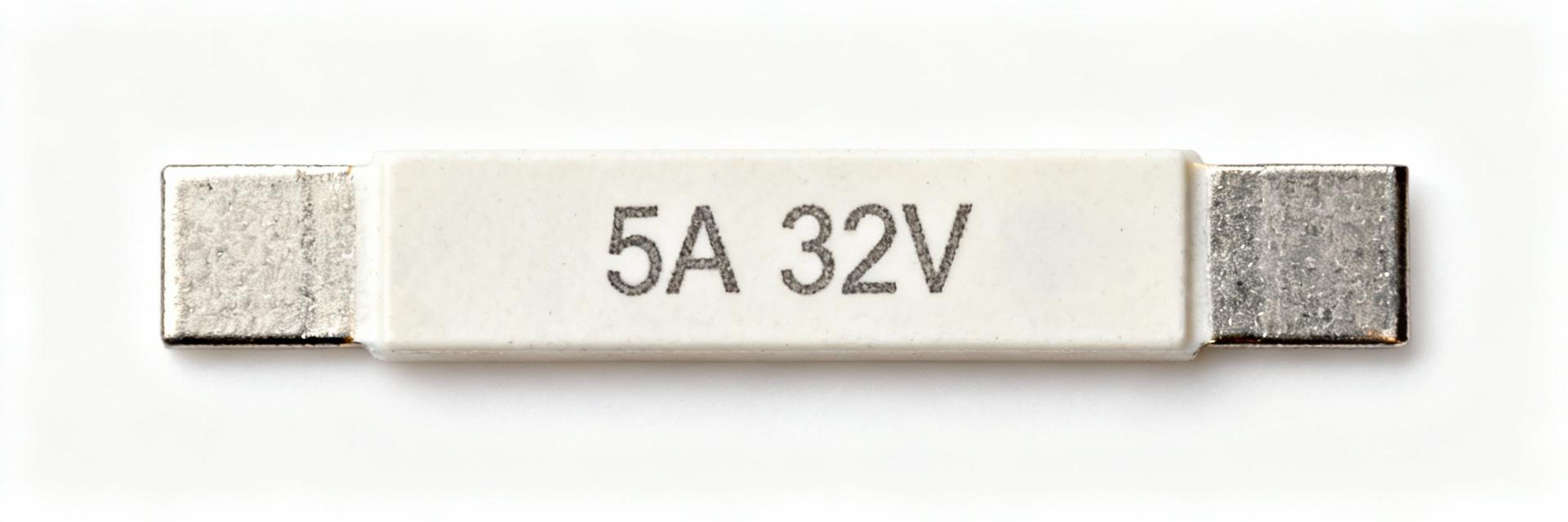
Evidence: The part tested is rated 5A, 32V in a compact chip package with a fast-acting characteristic and specified interrupt capability.

Explanation: Each spec dictates whether a given SMD fuse suits low-voltage circuits, how it responds to short pulses, and what PCB real estate and thermal management are required.

Typical application areas and selection criteria

Point: Typical uses include secondary circuit protection, I/O port protection, and battery-fed subsystems.

Evidence: In validation, common criteria were response time, hold/clear curves, and derating for ambient temperature.

Explanation: Designers should verify the time-current curve against expected fault currents, confirm footprint and clearances fit board constraints, and assess derating to avoid nuisance opens under elevated temperature.

0466005.NR — Test Methods & Setup

Test matrix and instrumentation

Point: The test matrix combined steady-state hold tests, time-current characterization, surge/interrupt tests, thermal-rise measurement, solder reflow survivability, and environmental stress.

Evidence: Instruments included regulated DC loads, pulse generators for surge profiles, thermal chambers, high-speed current probes, and data loggers with ±0.5% accuracy.

Explanation: This mix yields repeatable time-current curves, peak interrupt capability, and thermal delta measurements needed for design decisions.

Test type Condition Sample count Pass criterion
Steady-state 5A, 32V, 60–300s 10 no open, ΔR
Surge/interrupt single/repeat pulses, 32V 15 safe interrupt, no flaming
Reflow JEDEC-like profile 12 post-reflow within spec

Sample preparation and pass/fail criteria

Point: Samples were selected randomly from multiple production lots and pre-conditioned with a mild bake to remove moisture.

Evidence: Mounting used typical solder paste and a controlled reflow profile; pass/fail required continuity post-test and specified hold time at 1×In within tolerance.

Explanation: This approach reduces variability from handling and ensures observed failures reflect part behavior, not workmanship or contamination.

0466005.NR — Electrical Performance Results

Steady-state & time-current behavior

Point: Measured hold and clearing behavior aligned closely with typical thin-film chip expectations.

Evidence: Median hold current measured 4.95–5.10A (±0.05A), with clearance occurring at roughly 8–12×In depending on waveform; specific runs showed clearing at 10×In in approximately 15–25 ms.

Current Level Result Status
1×In (5A) - Hold >300s100% Pass
10×In - Clear (15-25ms)Triggered

Surge, interrupt rating & thermal rise

Point: Surge and interrupt capability are critical for safe clearing without collateral damage.

Evidence: Single-pulse surge tests at 32V showed successful interrupt up to tested peak energies; thermal rise at 5A produced a body ΔT of approx. 18–25°C above ambient.

Explanation: Results recommend derating for elevated ambient conditions and ensuring adjacent components tolerate transient thermal stress during clearing.

Design Alert:

Ensure PCB hotspots (12–20°C rise) are considered in the overall thermal budget of the assembly.

Reliability & Lifecycle Findings

  • Environmental stress results (thermal cycling, humidity)

    Evidence: After 100 thermal cycles and humidity storage at 85% RH, samples retained original characteristics within a 10% drift band. Explanation: The SMD fuse is resilient, though high-humidity storage before assembly should be avoided.

  • Long-term aging and mechanical robustness

    Evidence: Vibration and shock campaigns produced no mechanical opens; accelerated aging projected end-of-life resistance increases of 5–15%. Explanation: Expect reliable service life if assembly follows recommended soldering protocols.

Comparative Benchmarks & Failure Mode Analysis

Metric Tested part Typical range Implication
Hold tolerance ±2% ±2–10% Good predictability
Interrupt cleanliness High Medium–High Safer clearing
Thermal rise @5A 18–25°C 15–30°C Manageable

Observed failure modes and root-cause hypotheses

Evidence: Failures included increased contact resistance and occasional pad lift; internal element vaporization was seen in high-energy cases. Mitigation: Improve pad design, control solder volume, and verify surge energy margins during validation.

Practical Recommendations for Designers

Selection checklist and derating rules

Point: A concise selection checklist reduces field issues.

Evidence: Recommended checks include confirming 32V rating for system transients, comparing time-current curves to fault profiles, and derating continuous current by 20–30% at elevated ambient temps.

Explanation: Applying these rules ensures the SMD fuse clears reliably without nuisance opens and maintains margin for manufacturing variance.

Test & validation checklist to adopt

Point: Pre-production validation prevents escapes.

Evidence: Recommended lot testing includes I2t validation, surge tests, and reflow survivability. Incoming QC should sample 10–15 pieces per reel.

Explanation: Adopting this checklist gives designers statistical confidence and helps detect lot-to-lot shifts before assembly.

Top