Core Identification
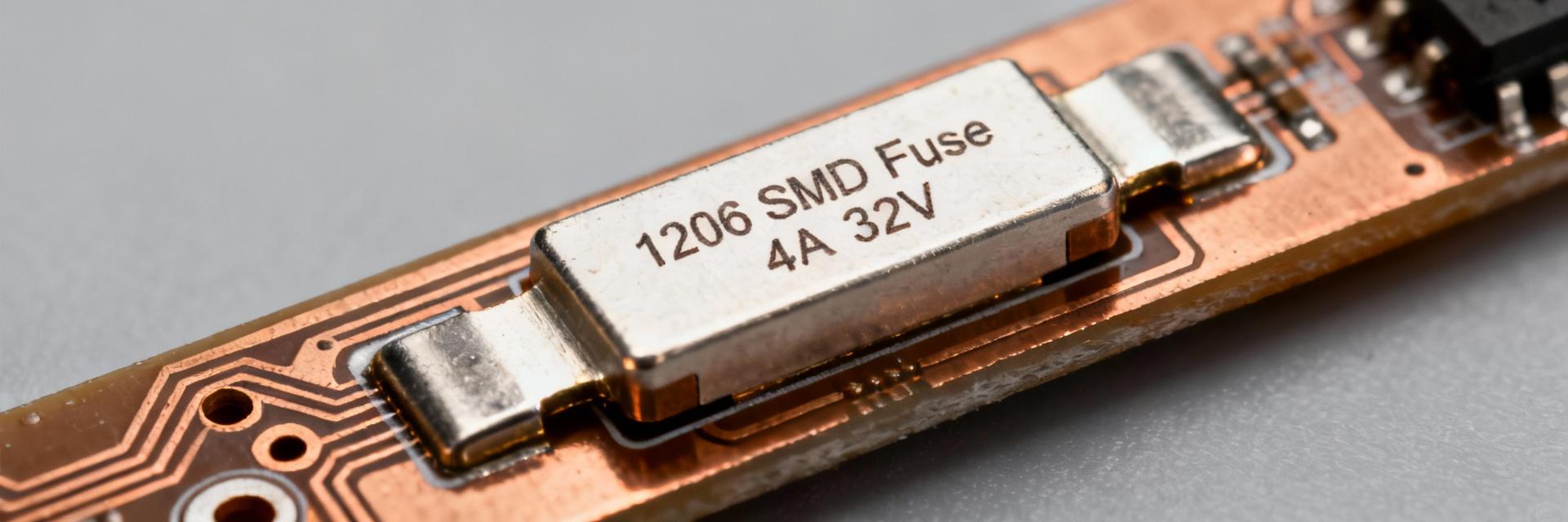
The 0466004.NR is a 1206 thin-film SMD fuse rated 4 A with a 32 V rating and an interrupt capability near 50 A, offering very fast-acting protection for low-voltage power rails.
Design Evidence
Key numbers—4 A rated current, 32 V rating, ~50 A interrupt rating, and low cold resistance—drive selection for USB, battery, and auxiliary rails.
Engineering Impact
These specs determine whether the device protects downstream semiconductors without excessive nuisance opens or excessive I²R loss.
This guide is a single-source walkthrough to read the part’s datasheet and apply it correctly in design. It summarizes mechanical, electrical, PCB, testing, and procurement checkpoints so engineers can verify the fuse against application needs. Use the datasheet checkpoints here to confirm time-current behavior, interrupt performance, footprint, and reflow limits before committing to a Bill of Materials (BOM) line item.
Background & Product Overview
Key Specs at a Glance
Quick visibility of the most relevant parameters speeds design decisions. Below table condenses the part’s critical rated values and packaging information. Scan these rows to confirm footprint, rated current, and interrupt capability before deeper datasheet reading; the main identification string appears in component references and BOMs.
| Parameter | Typical Value / Note |
|---|---|
| Part Number | 0466004.NR |
| Package Size | 1206 (3216 metric) |
| Fuse Type | Very fast-acting thin-film |
| Rated Current | 4 A |
| Rated Voltage | 32 VAC / 32 VDC |
| Interrupt Rating & Cold R | ~50 A interrupt, low milliohm cold resistance |
Datasheet Deep-Dive: Electrical & Mechanical Data
Electrical Characteristics & Fusing Behavior
Time-current curves and I²t define protective performance. Read the datasheet’s blow curves for specified ambient conditions, noting cold resistance and derating charts; typical behavior: at 200% In the device clears in the sub-0.1 s range, at 300% In in the sub-0.02 s range. Use the curves to predict whether the fuse will clear before downstream components fail.
Fusing Performance Visualization (Typical Blow Time)
If a 200% event clears in 0.05 s at 8 A, I²t = 8² × 0.05 = 3.2 A²s. Compare calculated I²t against downstream part let-through capability to ensure semiconductor survival during fault clearing.
Mechanical, Thermal Specifications & Packaging
- [•] Package dims and land pattern: Confirm mm values on datasheet to ensure precise PCB layout.
- [•] Reflow limits: Follow peak solder temperature and time-above-liquidus guidance to prevent internal element damage.
- [•] Packaging: Verify tape-and-reel counts and polarity/orientation for high-speed assembly feeders.
PCB Footprint & Reliability Considerations
Layout and thermal context influence fuse performance and inspection. Use the manufacturer-recommended land pattern and maintain solder fillets on both ends; provide thermal relief when adjacent large copper pours can alter heating. Confirm pick-and-place nozzle compatibility and define inspection points for fillet quality and part coplanarity after reflow to minimize tombstoning or poor joints.
Validation Checklist
- Time-current tests at 1.5×, 2×, 3× In.
- Interrupt test at max short-circuit current.
- Thermal cycling per assembly profile.
- Post-test visual inspection.
Procurement Check
- Record full part number and suffixes.
- Verify RoHS/Halogen-free markings.
- Specify reel size for production.
Summary
Treat the datasheet as the authoritative source—extract I²t and blow-time data, confirm mechanical lands and assembly limits, and record pass/fail metrics during qualification to ensure field reliability of the SMD fuse and associated system. Always operate at 70–80% of rated current where thermal margin is limited.
