The 0466001.NRHF is a very-fast acting 1206 (3216 metric) surface-mount fuse typically specified at 1 A continuous with a 63 V AC/DC maximum rating, a 50 A interrupt capacity, and a melting I²t ≈ 0.0423 A²s. These headline numbers determine board-level overcurrent protection by balancing safety (interrupt capacity and voltage rating), space (1206 SMD footprint), and response time (very-fast action) to limit damage to semiconductors and minimize system downtime. This guide covers identification, electrical/mechanical specs, time-current interpretation, selection methodology, and sourcing checks for design, procurement, and test engineers. The guide references the manufacturer datasheet for definitive verification of values, and it uses the keywords "0466001.NRHF", "SMD fuse", and "datasheet" where noted.
Quick Overview & Part ID (Background)
Part-number breakdown and what to expect
The part ID 0466001.NRHF encodes series and performance information: the numeric block signals series and nominal current while the suffix often denotes speed, packaging, or tape/reel trim. Designers should treat the suffix as a pointer to variant details and confirm exact meanings in the manufacturer datasheet. The identifier 0466001.NRHF is the reference to match on BOMs and purchase orders when verifying the 1 A / 63 V very-fast 1206 option.
At-a-glance specs table (Must-have quick reference)
Values above should be confirmed against the official manufacturer datasheet. When copying specs into design docs, cite the datasheet file name and page number for traceability.
Electrical & Mechanical Specifications (Data Analysis)
Electrical ratings & performance (Detailed)
Continuous current sets the normal operating limit; the 1 A rating is the maximum steady-state load before derating is required. Maximum voltage (63 V AC/DC) is a safety margin to ensure the fuse can interrupt without tracking or flashover. Interrupt rating (50 A) defines the worst-case fault current the device can safely clear.
*Example: The fuse clears well before the semiconductor limit is reached.
Example calculation: a downstream transient-sensitive semiconductor withstands 0.1 A²s; the fuse melting I²t of 0.0423 A²s indicates that at full melt the fuse lets through less energy than the component limit, implying good protection. Conversely, a 5 V rail with an inrush event of 2 A lasting 50 ms produces I²t = 4 × 0.05 = 0.2 A²s, which exceeds the fuse melting I²t and would likely blow the fuse. Refer to the manufacturer datasheet for exact time-current and resistance figures.
Mechanical dimensions & environmental limits
1206 SMD fuse footprint and land-pattern guidance (pad length/width, spacing, and solder fillet recommendations) are provided in the datasheet. Reflow profile notes (recommended peak temperature and time above liquidus) and moisture-sensitivity information must be followed to avoid damaging the fuse during assembly. The datasheet includes a dimension diagram and recommended PCB footprint—use those drawings directly.
Interpreting the Datasheet: Time-Current Curves & Test Conditions
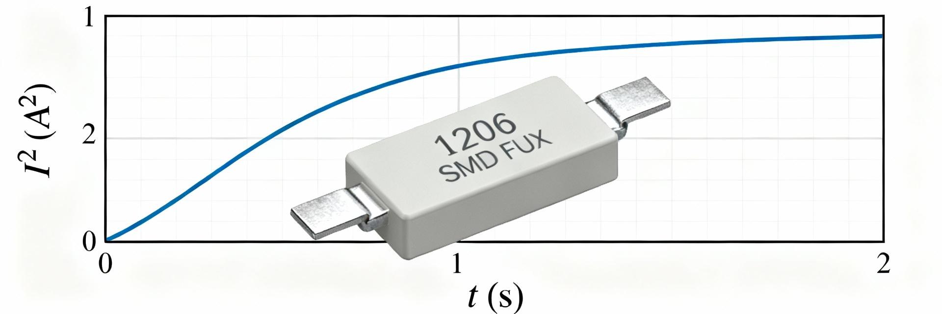
How to read time-current and I²t curves
Time-current curves plot current (log scale) vs. time-to-open (log scale). Read axes carefully: short-time (milliseconds) on the left shows very-fast behavior, long-time (seconds) on the right shows sustained overload response. Identify key points such as guaranteed blow at a multiple (e.g., 200% of rated current) and guaranteed survive points. Annotated curves from the datasheet illustrate how to translate an expected surge profile into fuse behavior.
Test methods, standards & rating caveats
Datasheet test conditions (ambient temperature, test circuit, pre-arcing allowance) affect measured times and interrupt ratings. Always confirm certificates and testing conditions in the official datasheet rather than assume interchangeability between similar part numbers.
Selection & Application Guide (Methodology)
Sizing Steps
- Measure continuous current.
- Estimate worst-case inrush.
- Select derating (75–85% typical).
- Compare fuse I²t to component limits.
- Verify voltage/interrupt margins.
PCB Best Practices
- Place close to the power source.
- Ensure adequate solder fillets.
- Avoid nearby high-heat components.
- Follow datasheet land patterns.
Troubleshooting, Alternatives & Procurement Checklist
Common failure modes and debugging steps
Typical causes of fuse blow include sustained overcurrent, repetitive surges above rated energy, soldering damage, or ambient overheating. Diagnose with a time-current tester, use thermal imaging to identify hotspots, and capture surge events with an oscilloscope.
Datasheet & sourcing checklist + cross-reference tips
- Package: 1206
- Rated Current: 1 A
- Max Voltage: 63 V
- Interrupt Rating: 50 A
- Melting I²t Verification
- Agency Approvals (UL/RoHS)
Summary
- ✔ The 0466001.NRHF is a compact 1206 very-fast SMD fuse rated 1 A / 63 V with a 50 A interrupt capacity—suitable where fast clearing and small footprint are priorities.
- ✔ Use manufacturer time-current curves and I²t comparisons to ensure protection and avoid nuisance blows from inrush events.
- ✔ Confirm mechanical footprint, reflow profile, and environmental limits from the official datasheet before layout and procurement.
