With compact devices driving demand for higher-density board-to-flex interconnects, the 0.5 mm-pitch FFC/FPC connector form factor is widely used where height and placement density are constrained. This quick-reference guide compiles datasheet-level details to help engineers confirm compatibility, design footprints, and test criteria before procurement.
Engineers will find compact spec tables, footprint guidance, electrical and environmental interpretation, plus actionable sampling and QC checks to validate parts in prototype and pre-volume stages.
Product at a glance: quick specs for 046214006010846+
The connector family represented here targets low-profile vertical board-to-cable interconnects. Key attributes for initial verification are pitch, position count, actuation style, and mounting method; confirm plating, insertion life, and current rating against the official datasheet before release to production.
Key mechanical & form-factor specs
| Parameter | Value | Note |
|---|---|---|
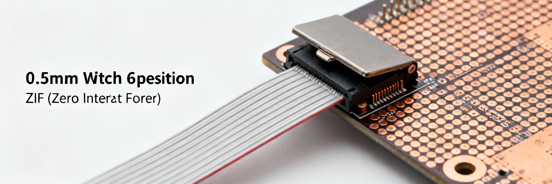
| Pitch | 0.5 mm | Critical for land pattern and cable type selection |
| Positions | 6 | Verify cable conductor count and polarity |
| Orientation | Vertical | Useful for tight-height stacks |
| Actuation | ZIF with slide lock | Low insertion force; confirm required sequence |
| Total height | ≤4.1 mm | Measure against bezel and mating cable clamp |
| Mounting style | SMT | Check tape-and-reel orientation for pick-and-place |
| Contact sides | Single-sided contact | Confirm cable orientation and mating face |
Visual Spec Comparison
What “0.5 mm pitch ZIF vertical SMT” means in practice
0.5 mm pitch increases board routing density but tight spacing demands accurate land patterns and controlled solder paste volumes. ZIF slide locks reduce insertion force but require a two-step handling sequence: open slide → insert cable → close slide. Common assembly pitfalls include insufficient solder fillet on pads and pick-and-place nozzle misalignment; both lead to tombstoning or poor joints after reflow.
Datasheet deep-dive: electrical, mechanical & environmental data
Mechanical Guidance
Pull top/side/bottom views and recommended land patterns. Critical tolerances include pad-to-pad spacing and slide-lock clearance. Solder mask keepouts should follow the land pattern to avoid masked fillets.
Electrical Interpretation
Interpret contact resistance, current rating per contact, and dielectric strength. Verify RoHS compliance and conformal-coating compatibility before applying protective layers.
How to select & integrate 046214006010846+ into your design
PCB footprint & assembly best practices
- • Land pattern verification: use datasheet recommended pattern as baseline; verify pad sizes and spacing in CAD.
- • Stencil aperture: use 60–80% paste coverage per pad for 0.5 mm pitch; reduce aperture for outer pads.
- • Pick-and-place: define nozzle size and center of gravity; use fiducials near the connector.
- • Reflow profile: follow standard Pb-free peak window; perform a trial reflow and inspect joints.
Quick comparison: when to choose alternatives
| Option | Pros | Cons |
|---|---|---|
| 0.5 mm vertical ZIF | Small footprint, easy mating | Lower current capacity, delicate handling |
| 0.5 mm right-angle | 90° exit for cable routing | Higher profile at board edge |
| Non-ZIF (low cost) | Robust contacts, simpler mechanics | Higher insertion force, risk of flex damage |
Datasheet & procurement checklist
Verification Steps
- Confirm 0.5 mm pitch and 6 positions.
- Verify drawings vs. layout.
- Confirm plating and soldering profile.
- Validate current and voltage ratings.
- Check packaging (Tape & Reel).
QC Recommendations
- ✅ Mate/unmate cycle test.
- ✅ Contact resistance measurements.
- ✅ Reflow solderability trial.
- ✅ Vibration and shock tests.
