High-current SMD fuses play a critical role in modern power electronics by protecting PCB power rails, battery packs, and automotive subsystems from damaging overloads and short circuits. This article analyzes the 0456040.DRSD SMD fuse with a test-focused, practical lens: electrical performance, thermal behavior, interrupt capability, and board-integration rules so US engineers can evaluate suitability quickly.
Product Overview & Key Specifications
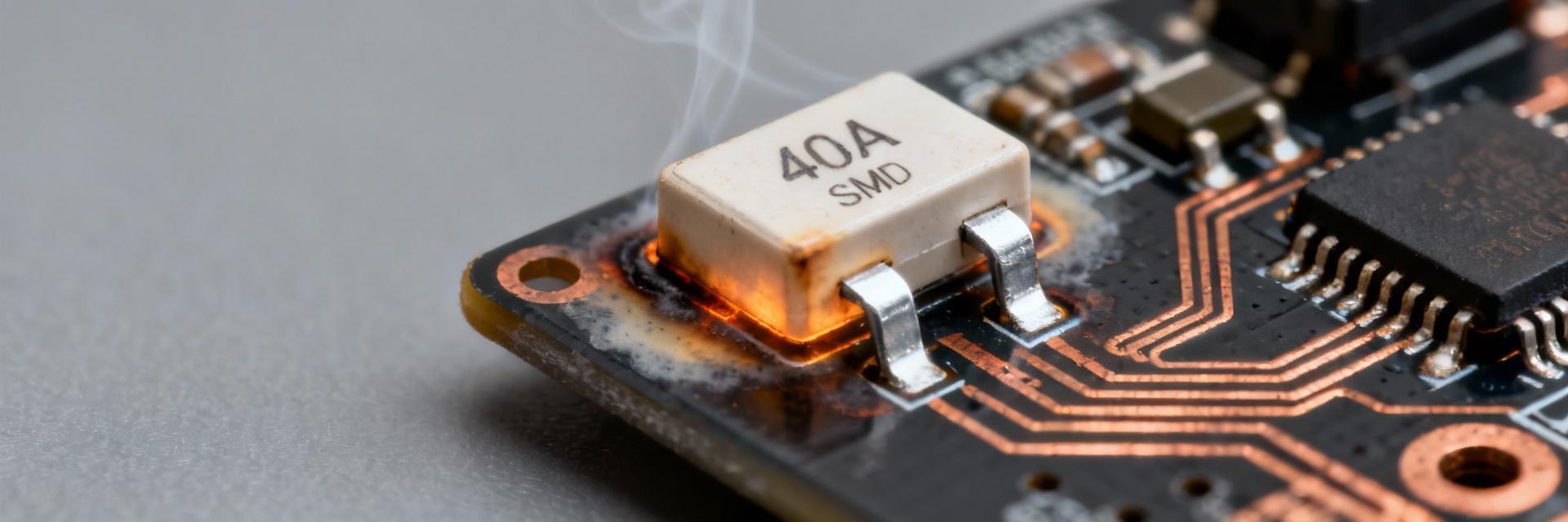
Form Factor, Marking and Nominal Ratings
Point: The 0456040.DRSD is a high-current surface-mount fuse intended for compact power designs. Evidence: typical implementations use a low-profile rectangular package sized for high-current PCB footprints and stamped marking with the part code and polarity/line orientation. Explanation: Ratings cited for selection context include 40A continuous current and a rated voltage commonly cited as 125V, noted here as 40A 125V for selection and derating discussions.
Typical Electrical Characteristics
Point: Designers need a concise table of electrical baseline metrics before test planning. Evidence: include fields for rated current (I-rated), rated voltage (V-rated), cold resistance, voltage drop at rated current, I²t and representative time-current points. Explanation: Presenting ranges (rather than single values) helps compare expected behavior across samples and supports quick margin checks during system integration.
| Field | Typical / Spec | Visual Reference |
|---|---|---|
| I-rated | 40 A |
|
| V-rated | 125 V |
|
| Cold Resistance | 3–8 mΩ | Low resistance path |
| Voltage Drop @ I-rated | 120–320 mV | Efficiency metric |
| I²t (Clearing) | Specified per test | Energy limit |
| Time-Current Points | 135%, 200%, 600% of I-rated | Tripping behavior |
Interrupt Performance & Electrical Limits
AC vs. DC Interrupt Behavior
Point: Interrupt capability differs for AC and DC due to current zero-crossing in AC that aids arc extinction. Evidence: DC interruption is typically the limiting case and should be reported as a separate A @ VDC rating; AC tests are quoted at specified VAC. Explanation: When documenting interrupt ratings, list both AC and DC A/V specs, then apply safety margins (e.g., 1.2–2× margin depending on system criticality) so designers map fuse interrupt capacity to worst-case fault scenarios.
Inrush, Surge and Short-duration Withstand
Point: Inrush and surge currents determine whether a fuse survives startup without nuisance opens. Evidence: short-duration withstand is captured by time-current curves and peak let-through (Ipeak and energy). Explanation: Provide excerpts from time-current curves showing behavior at common surge ratios (2×–10× Irated) and state peak interrupt energy limits so engineers can evaluate both transient endurance and system-level coordination.
Thermal Behavior & Temperature-rise Data
Temperature-rise vs. Continuous Current
Point: Continuous current rating depends on permissible temperature-rise under board conditions. Evidence: thermal-rise tests should report ambient, board mounting, copper area, and measured ΔT at discrete currents (e.g., 25%, 50%, 100%, 125% of Irated). Explanation: From a current-vs-ΔT curve or table, read the continuous allowable current at target ambient; this step prevents overheating and avoids premature opening or degradation.
PCB Layout and Thermal Derating
Point: PCB copper and vias form the dominant thermal path for SMD fuses and strongly affect ΔT. Evidence: practical rules include a recommended minimal copper area per pad, symmetric pad design, and via count to buried thermal planes. Explanation: Apply derating factors (for example reduce continuous rating by 10–30% for constrained copper or elevated ambient) and optimize thermal path—larger planes and more vias reduce fuse temperature and extend life.
Test Methods, Measurement Setup & Reproducibility
Recommended Test Setups
Evidence: use a stable source (DC for worst-case interrupt), current shunts with accuracy better than 1%, high-bandwidth voltage probes for waveform capture, and thermal probes/IR imaging on the fuse body.
Explanation: Capture time-to-open, peak let-through current, voltage drop under steady-state, and temperature rise during sustained currents.
Data Reporting & Repeatability
Evidence: report time-current tables, waveform snapshots, thermal images, and I²t calculations; specify sample size (min 5 samples) and preconditioning.
Explanation: Include measurement tolerances (current ±1–3%, temperature ±1–2°C) and pass criteria to aid qualification.
Integration & Selection Guidelines for Designers
- Choosing the Right Rating: Select I-rating 125–200% of max continuous current for intermittent loads or full rated for sustained loads, then apply ambient derating.
- Inrush Management: For high inrush motors or capacitor charging, choose higher I-rating or combine with startup limiting.
- Assembly Recommendations: Recommend symmetric pad footprints, robust solder fillets, and reflow profiles that reach proper peak temperatures without over-stressing the fuse.
- Mechanical Integrity: Implement strain-relief layouts to avoid mechanical fatigue and verify post-assembly cold resistance.
Failure Modes, Troubleshooting & Field Action Checklist
Point: Failures have diagnostic signatures that guide root-cause analysis. Evidence: open circuits from sustained overload, welded elements from interrupted high-energy faults, and gradual resistance increase from thermal degradation are common.
Field Mitigation Checklist
1. Verify actual current profile with logs | 2. Inspect solder joints and PCB copper | 3. Confirm part marking and orientation | 4. Run controlled bench fault tests | 5. Document replacement qualification.
Summary
Use interrupt, thermal, and steady-state performance data together to determine whether the 0456040.DRSD SMD fuse meets application needs for continuous current, inrush, and fault interruption. Bench-verify time-current behavior, peak let-through, and board-level ΔT under real mounting and ambient conditions before final selection.
