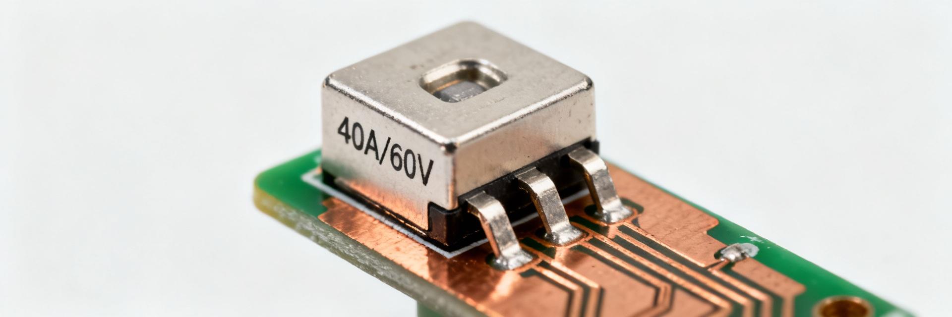
As board-level power densities rise across automotive, telecom, and battery systems, designers increasingly choose compact high-current SMD protection. The 0456040.DR is a common 40 A / 60 VDC NANO²-format option that balances size and interrupting capability.
This guide unpacks the datasheet, highlights electrical and thermal limits, and provides an actionable selection checklist so engineers can validate the part quickly and reduce risk during prototyping and production. We focus on measurable specs, practical calculations (Vdrop and power loss), and PCB/assembly guidance for reliable SMD fuse deployment.
Product Overview & Key Specifications
Part Identity, Package and Footprint
The part code 0456040.DR identifies a NANO² / square SMD block rated for 40 A continuous at low ambient temperatures and 60 VDC nominal.
| Dimension | Typical (mm) |
|---|---|
| Length (L) | 7.3 |
| Width (W) | 6.0 |
| Height (H) | 2.9 |
Recommended PCB pad geometry: two rectangular pads matching the device terminals with a solder mask opening slightly undersized for paste-stencil control. Use a 0.12–0.15 mm solder paste coverage on terminal areas to balance fillet formation and tombstoning risk. For thermal relief, avoid overly small pad-to-copper transitions under the device.
At-a-glance Electrical Summary
| Parameter | Typical Value | Units |
|---|---|---|
| Rated current | 40 | A |
| Rated voltage | 60 | V DC |
| Interrupting rating (example) | 150–600 | A (varies) |
| Characteristic | Fast-acting | — |
Electrical Characteristics & Performance Curves
Time-current Behavior and Fusing Characteristics
Time-current (T–I) curves show clearing time versus multiple of rated current and are the primary tool for coordination. Read the curve by locating the prospective fault current on the horizontal axis and tracing upward to the curve to find clearing time. For protection selection, choose a pick current that clears fast for sustained overloads but allows short inrush events without nuisance open.
Interrupting Rating, I²t and Energy Withstand
Interrupting rating (IR) denotes the maximum prospective fault current the fuse can safely interrupt. When I²t is listed, use it to compare the energy let-through against upstream protection—lower I²t reduces stress on wiring and downstream components.
Thermal Behavior, Resistance & Derating
DC cold resistance for this class of SMD fuse is typically in the single-digit milliohm range. Power loss scales exponentially with current (P = I²R), making thermal management critical.
Power Loss Visualization (at R = 2.5 mΩ)
Ambient Derating
Derating curves show reduced continuous current capacity as PCB temperature rises. Increase copper area and add thermal vias to dissipate heat; a double-sided heavy-copper plane under the fuse raises continuous capacity significantly.
Verification Tip
Validate with IR thermography and measure hotspot temperatures during representative current profiles to confirm safe operation within the fuse's thermal limits.
Reliability, Testing & Compliance
- Confirm thermal shock & mechanical vibration ratings
- Check solderability and recommended reflow profiles
- Verify surge and life-cycle test pass/fail criteria
- Search for agency recognition (UL/CSA/VDE)
- Map ratings to specific applications (Battery/Telecom)
- Confirm DC interrupting capability for energy packs
Datasheet Reading & Assembly Guidance
Quick-Check Steps
- Confirm full part code and revision
- Verify rated I, V, and Interrupting Rating
- Inspect T–I and derating curves
- Check mechanical drawing/land pattern
- Review recommended reflow profile
- Note storage and moisture sensitivity
Assembly Best Practices
Follow peak reflow temp and time-above-liquidus. Use controlled cooling to avoid thermal shock. Post-reflow, inspect solder fillets for wetting and planarity. Perform continuity checks before full system power-up.
Selection Checklist & Troubleshooting
Common Failure Modes
- Open-circuit from unexpected overcurrent
- Thermal degradation from poor heat sinking
- Failed solder joints due to thermal expansion
- Nuisance blowing from high-energy inrush
Selection Factors
- Current margin (typical 25–50%)
- Verified Interrupting Rating for voltage
- DC resistance and resulting power loss
- Package footprint compatibility
- Thermal derating for your specific PCB
Frequently Asked Questions
Is the 0456040.DR suitable for battery-pack protection? +
How should I verify Vdrop and power loss for an SMD fuse in my design? +
What PCB layout practices improve SMD fuse thermal performance? +
Summary
- 0456040.DR is a compact 40 A / 60 VDC SMD fuse; verify the exact interrupting rating on the official datasheet before production.
- Critical Checks: T–I curves, protection margins, interrupting rating / I²t values, and thermal derating relative to PCB copper.
- Procurement: Use the supplied quick-check to confirm mechanical, electrical, and environmental test coverage for production readiness.
