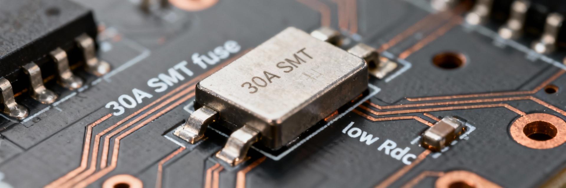
The 0456030.ER datasheet highlights a surface-mount, fast-acting fuse rated for high-current board-level protection: 30 A nominal current, 125 VAC max working voltage, and an exceptionally low DC cold resistance (~1.32 mΩ). This analysis targets design, test, and procurement teams seeking practical numbers and a bench test plan for seamless integration.
Quick Product Snapshot & Use Cases
At-a-glance Specs for Engineers
Key specifications required for part selection are concentrated in the datasheet summary tables. The datasheet lists nominal voltage, nominal current, fuse type (fast-acting), package dimensions, DC cold resistance, max voltage drop, and operating temperature limits. Engineers should prioritize these values for initial thermal and I2R calculations and footprint verification.
Typical Applications
Optimized for compact, high-current circuits where low series resistance and fast clearing are priorities. Typical domains include power modules, high-current rails, and industrial equipment with constrained PCB area. The combination of a small footprint and low resistance reduces I2R losses, enhancing thermal margins.
Mechanical & Thermal Specifications
Footprint & Soldering Constraints
Proper PCB footprint and reflow control are essential to reliability. The datasheet specifies recommended land pattern dimensions, peak reflow temperature, and time above liquidus. Designers must follow recommended pad sizes and solder paste stencil percentages to avoid tombstoning or internal element damage.
Thermal Behavior & Derating
Ambient heating significantly affects current-carrying ability. Designers should model trace and copper pour heating, adding thermal vias under large copper areas when needed. Always derate nominal current per datasheet guidance to maintain tested limits during sustained high-current operations.
Electrical Performance & Test Data
| Parameter | Nominal Value | Calculated Impact (at 30A) |
|---|---|---|
| DC Cold Resistance | ~1.32 mΩ | Voltage Drop ≈ 0.0396 V |
| Power Dissipation (P=I²R) | - | ~1.19 W |
| Package Size | 10.10 × 3.12 mm | High Power Density |
Time–Current & Interruption Performance
As a fast-acting fuse, the part clears quickly on overcurrent. Compare melting I2t against expected inrush energy; if inrush energy exceeds the fuse’s limit, nuisance opens will occur. Consider soft-start measures for high-capacitance loads.
Reliability & Test Protocols
Environmental Stress
Qualification tables indicate outcomes for temperature cycling, humidity, vibration, and mechanical shock. If your application involves high vibration, ensure mechanical anchoring is sufficient to mitigate failure modes.
Lab Test Checklist
- 4-Wire Rdc Check: Use precise milliohm meter.
- Surge Simulation: Capture clearing times.
- Thermal Monitoring: IR scan under full load.
Summary
- ✔ Low DC cold resistance (1.32 mΩ) makes this attractive for tight board-level rails; always verify I2R loss against system thermal budgets.
- ✔ Time–current curves and I2t are critical: simulate surge energy to avoid nuisance opens and ensure part selectivity.
- ✔ Follow the recommended land pattern and reflow guidance; incorporate survivability tests into your validation plan.
Frequently Asked Questions
What key numbers should engineers extract first from the 0456030.ER datasheet?
Engineers should extract nominal current, rated voltage, DC cold resistance, package footprint, time–current curve, melting/clearing I2t, and operating temperature range. These values enable I2R loss calculations, voltage-drop budgeting, and thermal derating assessments.
How should a test engineer validate cold resistance and performance?
Measure DC cold resistance with a 4-wire milliohm meter at ambient and after a standard reflow. For time–current performance, use a programmable current source with precise ramp control and a high-speed data logger to capture clearing times, comparing results against the datasheet curves.
What are quick fixes for common integration failures?
Address overheating by increasing copper area or adding thermal vias. Correct insufficient solder fillets by optimizing stencil aperture. Mitigate nuisance opens from inrush by adding soft-start circuitry or inrush limiters to keep energy below the melting I2t threshold.
