Engineers sizing overcurrent protection commonly consult aggregated catalog and lab datasets for fuses and surge-protection components to set safety margins. This article parses the 0443.750DR datasheet and extracts the critical electrical specs so designers can map rated current, voltage, interrupting capability, and thermal limits into system-level requirements with confidence.
What is the 0443.750DR? (Background)
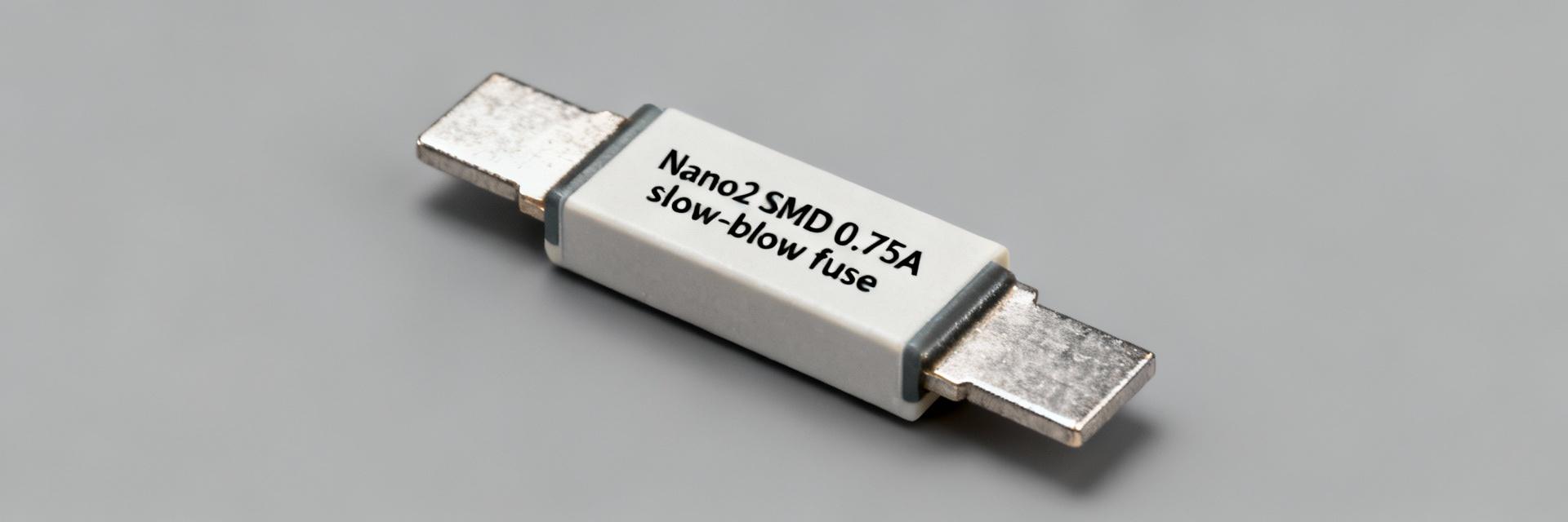
Point: The 0443.750DR is a surface-mount time‑lag (slow‑blow) fuse intended to protect circuits against sustained overcurrent.
Evidence: The datasheet classifies it in the Nano2 / 443 family with an SMD rectangular package and two end terminals for reflow mounting.
Explanation: That package and time‑lag characteristic favors inrush‑tolerant protection on board‑level AC and DC rails where repeatability and compact footprint matter.
Intended function and typical package
Point: Functionally the part interrupts overcurrent while tolerating short surges. Evidence: The datasheet indicates 0.75 A nominal rating and a 250 VAC working voltage class in a Nano2 SMD housing with recommended land pattern footprint. Explanation: Designers should orient the part to minimize thermal coupling to heat sources and follow the recommended footprint to preserve rated performance during reflow and in‑system thermal conditions.
Key use-cases and system-level role
Point: Typical applications include board-level mains input, power supplies, and I/O protection. Evidence: Because it is time‑lag, it handles inrush from motors or large capacitive loads while blowing on sustained faults. Explanation: System parameters that determine applicability are line voltage, expected steady‑state and transient currents, allowable series resistance and added capacitance, and required interrupting rating for safety compliance.
Complete electrical specifications (Data deep-dive)
Point: This section collates every guaranteed rating from the 0443.750DR datasheet so engineers can compare against system constraints. Evidence: Key fields include rated current, rated voltage, interrupting rating, operating/storage temperature, and time‑current behavior. Explanation: Extract these values into procurement and verification tables so test and design teams share a single source of truth.
Absolute maximum ratings & operating limits
| Parameter | Test condition | Value |
|---|---|---|
| Rated current | Continuous | 0.75 A |
| Rated voltage | AC or DC | 250 V AC |
| Interrupting rating | At rated voltage | 35 A (typical) |
| Operating / storage temp. | -55 °C to +125 °C | Range |
| Time‑lag characteristic | Defined in T‑I curve | Slow blow |
Current Handling Visualization
Key performance parameters to record
Point: Beyond absolute ratings, record hold/blow currents, I2t, voltage drop, and ambient derating. Evidence: The datasheet supplies time‑current curves (hold vs. time) and maximum voltage drop at rated current. Explanation: Typical vs guaranteed values must be logged; for example, measured cold‑hold current should match the guaranteed minimum to avoid nuisance opens in production.
Breakdown voltage behavior & protection characteristics (Data analysis)
Point: For a fuse, the term breakdown voltage is not the primary metric; instead dielectric strength and voltage rating govern insulation. Evidence: The 0443.750DR specifies a rated voltage and dielectric or creepage constraints rather than a Vbr figure. Explanation: When introduced, the secondary keyword breakdown voltage is used here to contrast TVS-style devices with fuses — fuses interrupt current rather than clamp voltage.
Interpreting breakdown voltage specs and tolerances
Point: Engineers must interpret the datasheet’s voltage rating and dielectric tests as the functional "withstand" limit. Evidence: The datasheet will list rated voltage and any dielectric withstand or insulation resistance tests. Explanation: Those values determine maximum continuous system voltage and spacing; they do not represent a switching or clamping threshold as with semiconductor arrestors.
Clamping, energy handling, and repetitive surge response
Point: Clamping voltage does not apply; energy handling for fuses is expressed as I2t and power dissipation. Evidence: Datasheet‑provided I2t and time‑current curves indicate energy required to blow at given currents. Explanation: Repetitive surges below the fusing threshold are tolerated, but repeated near‑blow pulses can age the element and shift time‑current behavior; apply derating for expected surge profiles.
How to test, verify, and measure the electrical specs (Method/guide)
Point: Verification requires time‑current testing, voltage drop measurements, and dielectric checks. Evidence: Standard test setups call for calibrated current sources, high‑precision voltmeters, thermally controlled fixtures, and a T‑I curve test jig. Explanation: Control ambient temperature, use four‑wire voltage measurement across the fuse, and follow the datasheet’s test waveform and conditioning recommendations to ensure repeatable results.
Recommended test setups & test conditions
Use step‑current and pulse‑current procedures to validate hold and blow behavior. Use programmable current sources, oscilloscopes to capture time to open, and temperature chambers. Minimize lead inductance and document cable routing.
Example measurement checklist
- Cold-hold current (within ±10%)
- Voltage drop at rated current
- T-I Curve conformity checks
- Insulation resistance post-blow
Application examples & selection scenarios (Case study)
1 Example: Low-voltage serial data line protection
Point: For a 5 V logic rail with expected 0.2 A steady state and 1.0 A short surge, choose a fuse whose cold‑hold exceeds steady current yet blows above sustained fault. Evidence: The 0.75 A rating and slow‑blow curve mean the part tolerates short surges but opens on prolonged 1.5–2× faults. Explanation: Include a small series resistor or ferrite if signal integrity is sensitive; document the schematic and BOM entry for reviews.
2 Example: Power-line surge protection with derating
Point: For a 120 VAC input with ambient 60 °C and frequent transients, derate continuous current and account for thermal stacking. Evidence: The datasheet’s ambient correction factors and time‑current curve suggest reducing allowable continuous current by a specified percent at elevated temperature. Explanation: Calculate expected lifetime by modeling worst‑case surge energy and applying a safety margin (for example, ≤80% of rated current for continuous operation).
Design checklist: safe limits, derating, and installation tips
Quick Safety & Derating Checklist
- Operate at ≤80% of rated current.
- Verify Interrupting Rating > Fault Current.
- Follow exact recommended PCB footprint.
- Minimize thermal coupling to MOSFETs/Inductors.
- Account for altitude/pressure if applicable.
Troubleshooting Common Issues
Common symptoms include nuisance opens, rising voltage drop, or thermal degradation. Remedies: Revise part selection, improve cooling, add series resistance, or move to a part with higher interrupting rating.
Key Summary
- The 0443.750DR is a 0.75 A Nano2 time‑lag SMD fuse; verify rated voltage and interrupting rating against system prospective fault current and board thermal profile.
- Critical electrical specs to record are rated current, rated voltage, interrupting rating, time‑current (I‑t) curve, voltage drop, and ambient derating factors for reliable selection.
- Testing should include cold‑hold, blow‑time at multiple currents, voltage‑drop measurement, and dielectric checks; document pass/fail bands and retain raw captures for review.
Recap: Use the 0443.750DR datasheet as the authoritative source to extract rated current, voltage, interrupting capability, and I‑t curves; verify electrical specs via the measurement checklist and apply conservative derating before finalizing the design.
