Point: This guide translates datasheet metrics and lab test reports into a concise reference for engineers evaluating the 0437004.WR part.
Evidence: Vendor documentation and distributor test summaries for this 1206 family highlight rated current, voltage class, trip curve, breaking capacity, and thermal limits.
Explanation: Engineers need a practical synthesis to map those Specs to board-level risks and qualification steps before committing a design.
Point: Use this document to prioritize tests and integration checks that reduce field failures.
Evidence: Common failure modes reported in distributor notes concentrate around reflow damage and off-curve trip behavior.
Explanation: A focused lab validation plan reduces costly respins and ensures the selected SMT fuse meets application margin and safety requirements.
Background: what 0437004.WR-class SMT fuses are and when to use them
Definition & form factor
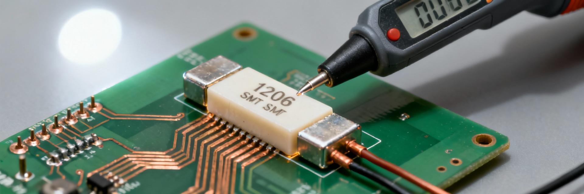
Point: 0437004.WR-class parts are 1206 (3216 metric) fast-acting SMD fuses used for board-level overcurrent protection.
Evidence: Datasheets for this family specify low-profile ceramic bodies and thin-film fuse elements optimized for reflow soldering.
Explanation: Designers should treat these as board-mounted sacrificial elements; common PCB constraints include limited board area, tight height envelopes, and required solder fillets for reliable joints. Diagram note: use a 1206 pad pattern reference and follow recommended land pattern tolerances.
Key ratings to check before selection
- ◈ Rated Current: Sets nominal load capacity.
- ◈ Voltage Rating: Ensures dielectric safety limits.
- ◈ I²t & Trip Curve: Defines coordination with upstream protection.
- ◈ Breaking Capacity: Determines survivability in short-circuits.
Technical specs: datasheet breakdown for 0437004.WR
Electrical specifications (how to interpret)
| Parameter | Typical Value (1206 Family) | Impact on Design |
|---|---|---|
| Rated Current | ~4 A Class | Nominal operating threshold; differs from trip current. |
| Voltage Rating | 32V - 63V DC | Max circuit voltage to prevent arcing after blow. |
| Breaking Capacity | Up to 50A @ Rated Volts | Survival limit during catastrophic fault events. |
Thermal & mechanical specifications
Operating Temp: -55°C to +125°C
Thermal derating is required for elevated ambient environments.
Soldering: Reflow Compatible
Follow peak soldering temp specs to avoid element damage or micro-cracks in ceramic body.
Test data & test methods: verifying 0437004.WR performance in-lab
Standard tests to run
Point: Essential bench tests include DC resistance, time-current (trip curve), surge/breaking-capacity, thermal cycling, and solderability/reflow bake.
Evidence: Lab procedures use source meters, high-speed current probes, and thermal chambers.
Explanation: DC resistance confirms low series loss; trip tests validate curve compliance; surge tests verify breaking capacity under fault energy.
Common Failure Modes
- No-Trip/Delayed Trip: Risk of downstream fire.
- Nuisance Trips: Due to improper I²t margin.
- Resistance Drift: After aggressive reflow cycles.
- Mechanical Cracking: Visible chipping or internal element damage.
Typical applications & troubleshooting case studies
Battery Protection
Used in regulator input rails and USB power management where rapid interruption is critical.
Telecom Signaling
Protection for data lines and signal paths where board space is highly constrained.
Field Diagnostics
Checklist: Measure DCR, inspect land pattern orientation, and identify upstream shorting faults.
Purchasing & integration checklist
Buying Checklist
- Confirm exact part-code suffixes.
- Verify packing format (reel/tape).
- Request independent test reports.
- Require lot traceability for production.
Qualification Plan
- Reflow qualification (peak temp soak).
- Functional verification under load.
- Margin testing (110% current soak).
- Define clear pass/fail criteria.
Summary
- Verify the 0437004.WR datasheet for exact Specs—current, voltage, trip curve, breaking capacity, and thermal limits—before selection.
- Run a concise qualification set: DC resistance, time-current (trip) tests, and surge/breaking-capacity testing; inspect after reflow.
- Follow a buying and integration checklist that confirms part-code, packing, and includes a pre-production validation plan.
Frequently Asked Questions
How do I read the time-current curve for an 0437004.WR-style SMT fuse? ▼
Point: Reading the curve shows hold times at given overcurrents and the trip envelope.
Evidence: Datasheet curves plot current multiple vs. time to trip with tolerance bands.
Explanation: Compare measured trip points to the curve; a part that trips consistently inside the band is compliant. For coordination, ensure upstream devices clear earlier or that I²t limits match upstream protection goals.
What reflow precautions are needed for a 1206 SMT fuse? ▼
Point: Follow the fuse reflow temperature profile and limit dwell at peak temperature.
Evidence: Datasheets specify maximum peak temperature and time above liquidus for soldering.
Explanation: Excessive thermal exposure can cause microcracks or element alteration leading to failures; use recommended land pattern, avoid mechanical flex, and perform post-reflow electrical checks.
What are practical pass/fail criteria for production sign-off of an SMT fuse? ▼
Point: Define electrical, mechanical and thermal criteria for sign-off.
Evidence: Common criteria include trip behavior within datasheet tolerance, no increase in DC resistance over specified thresholds, and no visible damage after thermal cycling.
Explanation: Require a sample reel test with functional trip, surge survival as specified, and documented lot traceability before releasing the part to production.
