The 1206 SMD fuse is a compact overcurrent protection element widely used on modern PCBs. Aggregated datasheet ranges show rated currents from about 0.1 A up to ~10 A, voltages to ~125 VAC / 125 VDC, and breaking capacities from ~50 A to several hundred amps depending on construction. These ranges make the 1206 form factor appropriate for low- to medium-power protection in consumer, industrial, and automotive-adjacent electronics where board space is constrained.
This guide condenses how to read fuse specs and apply them in design and procurement. The sections cover form factor, construction types, electrical ratings, time-current interpretation, datasheet checklists, failure modes, and qualification tests. Engineers can use this to speed part selection, reduce field failures, and define minimal laboratory acceptance criteria before production.
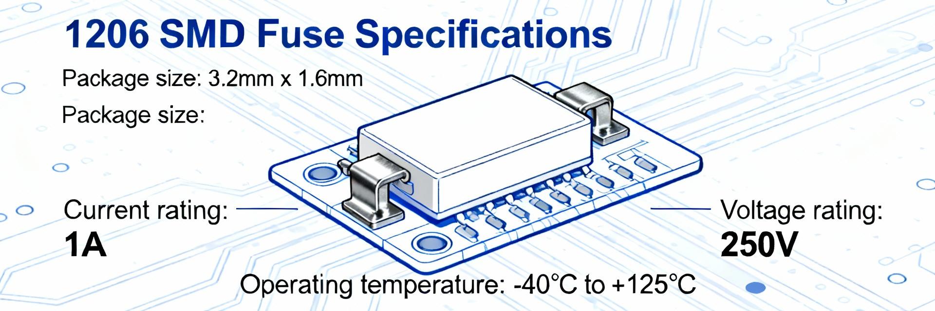
Background: 1206 SMD Fuse Form Factor, Construction, and Common Uses
What "1206" Means: Package Dimensions & Standards
"1206" denotes the chip nominal footprint approximately 3.2 x 1.6 mm. Industry footprint conventions translate 1206 to ~3.2 mm by 1.6 mm (0.126" x 0.063") with recommended pad geometry following IPC land-pattern guidance. Accurate pad spacing and copper land pattern control solder fillet and thermal relief, directly affecting solderability and electrical resistance of the fuse on the PCB.
| Dimension | Value (mm) | Value (inch) |
|---|---|---|
| Chip body | 3.2 x 1.6 | 0.126 x 0.063 |
| Typical pad spacing | ~1.0–1.2 | ~0.039–0.047 |
| Recommended land pattern | Per IPC−7351 footprint | — |
Typical Construction Types and Environment Ratings
1206 SMD fuses appear in thin-film, solid-body, and lead-free thin-film constructions. Datasheets commonly list reflow compatibility, RoHS compliance, max operating temps and storage limits; many parts specify operating ranges to +125°C and storage limits to +85°C. When comparing fuse specs, verify solder reflow profile, max operating temperature and shelf limits since elevated temps change hold/trip currents and long-term reliability.
Key Electrical Specifications: Current, Voltage, Breaking Capacity, and Time-Current Behavior
Rated Current and Voltage: Ranges, Derating, and Test Conditions
Rated current and voltage define safe continuous use and insulation boundaries. Typical rated-current ranges span ~0.1 A to 10 A and voltage ratings often up to 125 VAC / 125 VDC; datasheets list hold/trip current definitions and test conditions. Apply ambient derating (example: a conservative 10–20% reduction at 60°C) and check tolerance and test setup to ensure the chosen fuse meets continuous operating and transient conditions.
| Rated Current | Rated Voltage | Derating @ 60°C | Typical Tolerance |
|---|---|---|---|
| 0.1 A – 10 A | ≤125 VAC / 125 VDC | ≈10–20% | ±10–20% |
Breaking Capacity, I2t, and Interpreting Time-Current Curves
Breaking capacity and I2t govern fault clearing and energy absorption. Datasheets list breaking capacities from ~50 A to several hundred amps and provide I2t or clearing energy plus time-current curves. Use I2t to ensure upstream components survive clearing; read time-current curves to see clearing time at multiples of In (e.g., 2× may take seconds, 5× hundreds of milliseconds, 10× tens to hundreds of milliseconds depending on fast or time-lag design).
How to Read and Compare 1206 SMD Fuse Datasheets (Practical Checklist)
Datasheet Checklist: Required Fields to Compare
A standardized checklist speeds side-by-side evaluation. Critical fields include package dimensions, rated current/voltage, time-current curve, breaking capacity, I2t, ambient derating, reflow profile, mechanical life, resistance, and referenced test standards. Score candidates by a one-line method (pass/fail per field or numeric weighting) and prioritize fields tied to your fault profile and PCB thermal environment.
- Package dimensions & land pattern
- Rated current & voltage
- Time-current curve and tolerance
- Breaking capacity & I2t
- Reflow/solderability and operating temp
- Referenced test standards
Comparing Time-Current Curves, Tolerances, and Test Conditions
Small differences in test conditions materially change real-world behavior. Two parts with similar In can show different clearing times if tested at different ambient temps, fixture resistances, or sample sizes. Request supplier test-fixture details, sample size, ambient temperature and thermal mass used for curves; prefer datasheet data that matches your board-level thermal conditions for meaningful comparisons.
Performance Examples & Common Failure Modes (Lab vs Datasheet)
Fast-acting vs Slow-blow 1206 Variants
Fast-acting and time-lag variants serve different transient profiles. Fast-acting types clear quickly at moderate multiples of In, while time-lag tolerates inrush (e.g., capacitive or motor starts) and clears on sustained overload. Select In so normal inrush stays below the fuse trip curve while faults exceed the clearing threshold with adequate margin.
Thermal, PCB Layout, and Soldering-related Failures
Thermal environment and soldering influence fuse performance and reliability. Large copper pours, adjacent power parts, or poor solder joints change local temperature and resistance; tombstoning and cold joints are common solder-related failure modes. Use thermal relief, limit copper area under pads, validate reflow profile, and specify solderability/x-ray checks.
Selection & Qualification Playbook: Specifying, Testing, and Documenting
Design Selection Steps and Sample Part-spec Template
Follow a stepwise selection flow to capture electrical and assembly constraints. Recommended steps: define system fault current, determine breaking capacity and I2t margin, choose rated voltage/current with derating, verify reflow and board compatibility, and document standards. A concise part-spec template should include In, Vmax, I2t requirement, breaking capacity, reflow temp, operating temp, footprint, and referenced test standards.
Qualification Testing & Procurement Acceptance Criteria
Define tests and lot-acceptance criteria to de-risk production. Recommended tests: destructive breaking-capacity validation, thermal cycling, solderability, sample x-ray for assembly voids, and time-current verification; use statistically appropriate sample sizes and documented pass/fail thresholds. Require labeling and traceability fields (lot, datecode, reel) and minimal lab reports before production approval.
Summary
- The 1206 SMD fuse is a compact, versatile protection device; key decisions are rated current/voltage, breaking capacity/I2t, and time-current match to fault profiles—use the datasheet checklist in BOM reviews.
- Compare fuse specs beyond In: verify test conditions, ambient derating, I2t and breaking capacity for your expected fault current and board thermal environment to reduce field failures.
- Require minimal qualification: destructive breaking-capacity tests, solderability checks, and traceable lot labeling before production to ensure supplier consistency and meet system ratings.
