Scope
Point: This article focuses on the 0435001.KR as an example 0402 fuse and answers practical questions engineers face. Evidence: sections cover electrical specs, time‑current reading, lab test items, application layout examples, and a selection checklist. Explanation: the goal is concise, data‑driven guidance so designers can match datasheet curves to real‑world currents in constrained PCB layouts.
Compact fuse background: what 0402 SMD fuses are and where they’re used (Background introduction)
Physical form factor & industry naming
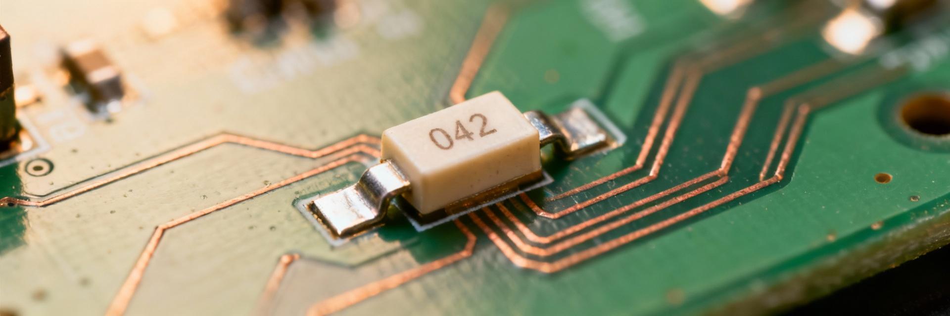
Point: The 0402 SMD fuse denotes a 0.04" × 0.02" (1.0 × 0.5 mm) chip in standard industry naming. Evidence: thin‑film or chip fuse construction uses patterned fuse elements on ceramic substrates rather than wire windings. Explanation: this construction yields predictable, very‑fast thermal response and low parasitic inductance, and parts ship on tape/reel for automated board‑mount assembly.
Typical use cases in modern electronics
Point: 0402 SMD fuse for wearable devices and similarly compact products is common due to space and thermal limits. Evidence: target applications include wearables, mobile, IoT sensors, and secondary rails on battery systems where steady currents are small but fault protection is required. Explanation: the tiny footprint reduces layout area and permits placement near connectors and sense elements while minimizing thermal interaction when routed correctly.
Key electrical specs for 0435001.KR and how to interpret them (Data analysis)
Nominal ratings: voltage, current, and fuse type
Point: Nominal ratings define where the fuse can be applied safely. Evidence: for the 0435001.KR example, expect a DC voltage rating around 32 V and a nominal current rating of 1 A, with a very‑fast/fast blow thin‑film classification. Explanation: voltage rating limits maximum circuit voltage; current rating and blow type indicate how long the fuse withstands overloads and whether it tolerates short surges in DC rails.
Time-current curve, hold vs. trip current, and breaking capacity
Point: Time‑current data and breaking capacity are the core performance data designers read to size fuses. Evidence: a time‑current curve shows trip time at multiples of In, Ihold defines steady‑state pass current, Itrip defines the level that must clear within specified time, and breaking capacity specifies maximum interruptible fault current. Explanation: use safety margins (commonly Ihold ≥ 125% of max steady current) and ensure breaking capacity exceeds worst‑case fault current on the protected rail.
Measured performance: lab test items & realistic expectations (Data analysis / methods)
| Test Category | Key Metrics / Conditions | Design Impact |
|---|---|---|
| Time-Current | Trip time at 2×, 5×, and 10× In | Defines protection speed |
| Thermal Profiling | Ambient temperature derating (25°C baseline) | Prevents nuisance blowing in hot environments |
| Electrical Resistance | Voltage drop at rated current | Efficiency & thermal management |
| Reliability | Solderability & mechanical stress tests | Ensures long-term assembly integrity |
Point: Lab results often deviate from ideal datasheet curves due to setup and assembly variables. Evidence: differences arise from PCB thermal mass, conductor width, and measurement latency; manufacturers state tolerances on curves. Explanation: translate curves into design margins by derating for ambient and board heating, and choose Ihold margin (e.g., ≥125%) so normal pulses or measurement error don't cause nuisance opens.
Application examples & layout considerations (Case studies / practical)
Example A: protecting a USB power rail in a compact IoT module
Point: Protecting a USB power rail requires balancing steady draw, transient pulses, and board constraints using a 0402 SMD fuse. Evidence: if USB device steady current is 350 mA with occasional 1 A peaks, choose a fuse with Ihold > 440 mA and known trip behavior at 2–3× In; place fuse close to the connector. Explanation: route wide power traces to reduce heating, add thermal relief patterns to avoid unintended fuse derating, and maintain short return paths to limit fault energy.
Example B: battery-protection pre-regulator for wearable sensor
Point: Battery pre‑regulators need fuses that handle inrush and board stress. Evidence: wearable sensors may see brief inrush to capacitors of several amperes; a 0402 fuse must either tolerate the surge or be paired with soft‑start circuitry. Explanation: mount the fuse near the battery connector, ensure mechanical support on the tiny footprint, and verify reflow and mechanical stress tests to prevent cracking during normal handling.
Selection checklist & implementation best practices (Actionable guidance)
Quick selection checklist
- Confirm Ihold (≥ 125% rule) and Itrip.
- Verify Voltage Rating (e.g., 32V).
- Check Breaking Capacity vs max fault.
- Analyze Time-Current Curve fit.
- Account for Ambient Derating.
- Confirm Packaging (Tape/Reel).
PCB layout & assembly notes
Point: Layout and process determine in‑board performance. Evidence: accurate footprint with fillet‑friendly pads, conservative stencil openings, and moderated reflow peaks. Explanation: reduces tombstoning and mechanical stress—inspect solder joints post‑reflow and perform vibration tests.
