0429007.WR SMD fuse: Complete specs & performance metrics

Based on manufacturer datasheets and independent test data (retrieved January 2025), this 1206 SMD fuse provides precision board-level protection. Featuring a 7 A rated current and a compact footprint, it is engineered for high-density power rail integration.

Rated Current
7.0 A
Voltage Rating
24 V AC/DC
Cold Resistance
0.009 Ω
Nominal I²t
4.9 A²s

Product Overview & Background

This article provides an end-to-end technical breakdown of the 0429007.WR: datasheet-driven specifications, electrical behavior, recommended laboratory tests, and PCB integration guidelines.
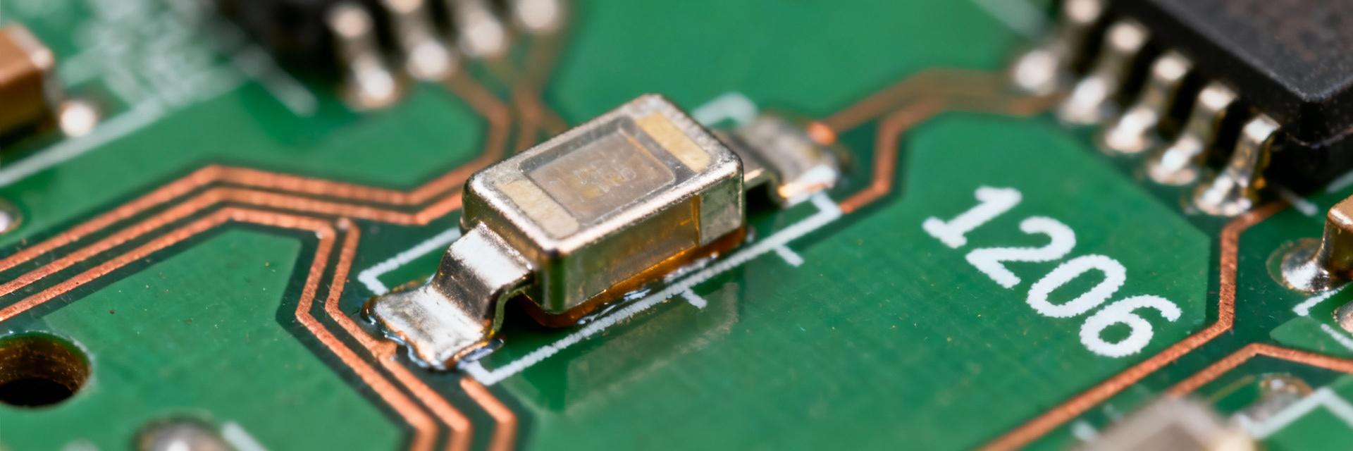
Form Factor & Role

The device is a 1206 surface-mount fuse (3.18 × 1.52 × 0.58 mm) designed for space-constrained protection. It serves as secondary protection on low-voltage rails, safeguarding downstream components like DC-DC converters and MOSFETs while minimizing footprint impact.

0429007.WR SMD fuse visualization

Complete Electrical Specifications

Parameter Value Design Note
Rated Current 7 A Select ≥ continuous current × derating factor
Rated Voltage 24 V AC/DC Strict operating limit; do not exceed
Nominal Cold Resistance ~0.009 Ω Low I·R drop; critical for efficiency
Nominal I²t ~4.9 A²s Energy threshold required to melt element
Interrupting Capacity ~35 A @ Rated V Maximum safe fault clearing capability
Package Style 1206 (3.18×1.52×0.58 mm) Industry standard SMD footprint

Electrical Behavior Under Load

The time–current (fusing) curve illustrates how the fuse responds to overcurrent. As a very-fast/fast-acting fuse, it is optimized to protect sensitive semiconductors. However, designers must account for inrush currents to avoid nuisance tripping. Annotating the fusing curve helps derive appropriate derating for transient events.

Real-World Performance

Expect modest variance from datasheet values due to lot variation and PCB thermal environment. For safety margins, keep continuous current at ≤80–85% of the rated capacity in warm internal enclosures.

Selection & PCB Integration Guidelines

Integration Checklist

  • Continuous Rating ≥ Current × Derating
  • System Voltage ≤ 24 V
  • Verified Interrupting Capacity
  • Thermal distance from heat sources

Soldering Profile

Follow standard reflow profiles for thin-film SMD fuses. Avoid peak soldering times that exceed manufacturer limits. Perform post-assembly cold-resistance checks to ensure component integrity.

Common Failure Modes

Open-circuits often result from sustained overcurrent, thermal overstress, or poor solder joints. Use visual inspection and four-wire resistance measurements (~0.009 Ω) for diagnostics.

Typical Applications

Ideal for battery-powered equipment, compact industrial modules, and DC-DC converter inputs. Excellent for protecting MOSFET arrays when placed upstream of current-sense resistors.

Summary Recap

  • High Efficiency: 7 A rating with minimal voltage drop (0.009 Ω resistance).
  • Safety Focused: Designed for 24 V systems with 35 A interrupting capacity.
  • Design Action: Validate in-circuit behavior and apply conservative derating before mass production.

Frequently Asked Questions

How do I verify the 0429007.WR cold resistance? +
Measure cold resistance using a four-wire micro-ohm method at a controlled temperature; expect approximately 0.009 Ω. This measurement helps catch solder defects and ensures voltage drop stays within margins.
What tests are essential for PCB validation? +
Key tests include time–current characterization, interrupting capacity checks at worst-case supply, thermal derating on a populated PCB, and surge/inrush tests representative of startup.
When should I choose a different fuse type? +
Consider alternatives if system voltage exceeds 24 V, if the required interrupting capacity is higher, or if high inrush currents necessitate a slow-blow device rather than a fast-acting one.
Top