0428195213 Connector: Complete Specs & Pinout Cheat Sheet
A definitive guide for engineers and technicians to confirm form factor, pinout configurations, and professional installation standards.
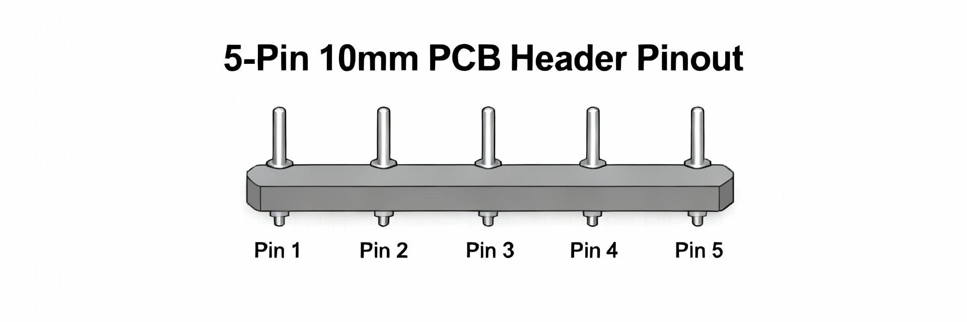
The 0428195213 connector is a 5-position, 10.00 mm pitch, vertical through-hole header commonly specified in industrial BOMs and product catalogs for robust signal and moderate-power wiring.
"This compact guide delivers data-driven highlights so engineers can confirm form factor and apply best practices quickly. Refer to the official datasheet for absolute tolerances."
✓ At-a-Glance: What the 0428195213 connector is
Form factor & mechanical overview
Point: 5-position, 10.00 mm (0.394") pitch, vertical through-hole board header.
Evidence: Right-angle/vertical wire-to-board header with upright mating orientation and solder-pin terminations through PCB holes.
Explanation: Mounting provides mechanical robustness for repeated mating; designers should use mechanical anchors to resist leverage during insertion.
Common applications & compatibility
Point: Suits mixed signal and low-to-moderate power connections.
Evidence: Industrial control panels, sensor harnesses, and small device power distribution.
Explanation: Large pitch enables heavier wire gauges (AWG 22–16) and simplifies field serviceability. Confirm mating series and polarization in procurement.
| Item | Value |
|---|---|
| Part type | 5-position vertical through-hole header |
| Pitch | 10.00 mm (0.394") |
| Mounting | Through-hole, vertical |
| Housing material | High-temp thermoplastic (e.g., Nylon 66) |
| Contact material | Brass or phosphor bronze; tin or gold plating |
Datasheet & Key Specs for the 0428195213 connector
Mechanical specifications (dimensions, tolerances)
Point: Mechanical dimensions define footprint, hole size, and clearance for assembly. Key items include pitch tolerance, recommended PCB footprint, and drill/hole plating specification.
Explanation: Match the footprint exactly: typical through-hole diameters range 0.9–1.2 mm; ensure solder fillet allowance and keep copper clearances for reliable joints.
| Parameter | Recommendation |
|---|---|
| Pitch | 10.00 mm |
| Suggested PCB hole | 0.9–1.1 mm plated through-hole |
| Recommended pad | Annular pad for robust wave/hand solder fillet |
| Pin protrusion | 1.5–2.5 mm minimum for reliable solder fillet |
Electrical specifications (current, voltage, contact resistance)
Point: Ratings vary by plating and wire gauge; typically accepts AWG22–16 and currents up to single-digit amps depending on geometry.
Check per-contact rules
| Spec | Notes |
|---|---|
| Rated voltage | Typical low-voltage industrial ranges |
| Contact resistance | Check typical mΩ value; use threshold for QC |
Pinout & Wiring Cheat Sheet
Pin numbering convention and diagram
Define whether numbering uses the mating side or solder side view; mark pin 1 with a physical marker or silk. Recommended convention: count left-to-right when viewed from the mating side with the latch on top.
Wiring examples & color mapping
- ▶ Power Mapping: Use AWG 22–16 for power lines. Avoid single contacts for high-current without parallelization.
- ▶ Signal Mapping: Use AWG 24–28 for signal lines; employ strain relief and routing clamps.
- ▶ Configuration: Typical uses include single-ended signal + power (V+, GND) or 2-wire power with three spares.
Installation, Testing & Troubleshooting
PCB footprint best practices
Checklist items include hole diameter, solder-mask clearance, and anchor points. Wave solder or selective soldering is common; provide mechanical anchors if the connector sees repeated mating forces.
Common faults & diagnostic steps
Faults include intermittent contact, bent pins, and high resistance. Steps: visual inspection, continuity test, and measure contact resistance with four-wire method.
| Symptom | Cause | Action |
|---|---|---|
| Intermittent connection | Debris or incomplete solder fillet | Inspect, clean, reflow |
| High contact resistance | Corrosion or plating wear | Measure mΩ; replace if high |
| Bent pin | Mechanical impact | Straighten carefully or replace |
Quick Reference: Purchasing & Alternatives
Pre-purchase checklist
- Verify full part number & position count
- Check plating finish (Tin vs Gold)
- Confirm RoHS/Compliance status
- Packaging (Tape & Reel vs Bulk)
Alternative paths
Search by 10.00 mm pitch and 5 positions. Consider gold-plated variants for harsh environments. Always validate mating compatibility before switching vendors.
Summary
- ● The 0428195213 is a 5-position, 10.00 mm pitch header for moderate-power; confirm variants in the official datasheet.
- ● Follow recommended PCB hole and solder fillet practices; select wire gauges AWG 22–16 for power.
- ● Run regular assembly and test checklists—visual, continuity, and resistance checks—to ensure long-term reliability.
