Point: This article translates the AD5560 datasheet into practical test plans for precision bench evaluation. Evidence: The datasheet highlights resolution, accuracy bands, and thermal constraints that often determine suitability for regulated current sourcing. Explanation: Engineers will get actionable setups, charts, and guardbanding rules to reconcile published specs with measured behavior for robust designs.
AD5560 Overview and Key Specs (background)
Block-level functional summary
Point: The device integrates programmable force and measure channels, an internal DAC and dedicated power/thermal domains. Evidence: The functional block organization in the datasheet groups the DAC, output stage, measurement sense, and power-management domains. Explanation: Understanding block mapping clarifies which bench connections exercise the DAC versus the output driver and where to place sense resistors and thermal monitoring on the PCB.
Critical electrical specifications to watch
Point: Prioritize supply ranges, DAC resolution, accuracy/linearity, and thermal dissipation during initial evaluation. Evidence: Datasheet tables list voltage and current operating bands, resolution in bits, INL/DNL and offset drift specs that affect precision. Explanation: Early focus on these specs lets engineers size supplies, select measurement ranges, and define pass/fail limits for bench verification before extensive system integration.
Datasheet Deep-Dive: Electrical Characteristics (data analysis #1)
Static performance: accuracy, offset, drift (datasheet interpretation)
Point: Read static tables as paired error sources: offset, gain, INL/DNL and temperature coefficients. Evidence: The datasheet separates initial errors and temperature-related drift by clause and table, often specifying test conditions. Explanation: Translate each row into re-test steps—measure offset at zero setpoint, sweep full-scale to characterize gain and INL, and run temperature ramps to quantify drift against datasheet limits.
Dynamic performance: bandwidth, settling time, noise
Point: Dynamic specs determine measurement throughput and stability after setpoint changes. Evidence: Datasheet figures define settling time at specified load and output steps, plus noise density or RMS noise over bandwidth. Explanation: Engineers should extract noise PSD curves and step response plots from the datasheet and replicate those measurements to validate filtering, sampling rates, and control-loop interactions in the target system.
Datasheet Deep-Dive: Operating Limits & Thermal Behavior (data analysis #2)
Absolute maximums and safe operating area
Point: Distinguish absolute maxima from recommended operating ranges to avoid latent failures. Evidence: Datasheet absolute-rating tables list maximum voltages, currents, and junction temperatures separate from the normal operating tables. Explanation: Use absolute ratings to define catastrophic limits and set softer guardbands in firmware/hardware so transient conditions, like fault recovery, cannot exceed safe operating area.
Recommended operating conditions and power sequencing
Point: Follow recommended supply ranges and sequencing to ensure deterministic behavior at startup. Evidence: Datasheet sequencing notes and supply tolerance tables specify voltage ramps and timing constraints for stable measurement and to avoid latch-up. Explanation: Convert those constraints into simple power-up scripts and hardware sequencing (e.g., controlled ramping or supervisor gating) and document guardbands for margin under worst-case temperature.
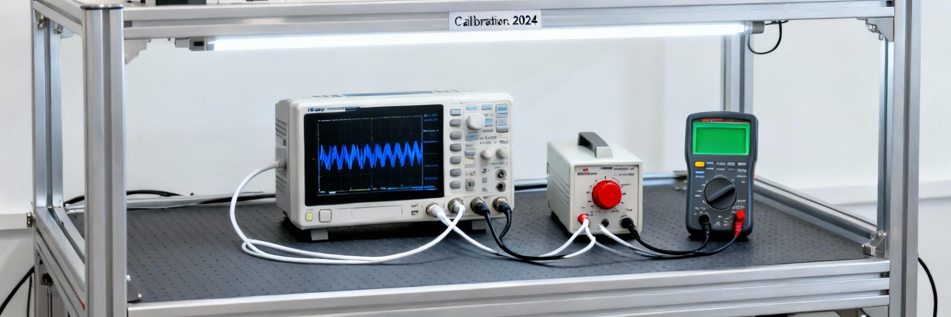
Reproducing Test Data: Lab Setup & Measurement Methodology (method guide)
Recommended test setups to reproduce datasheet plots
Point: Match the datasheet’s test conditions when reproducing plots to allow direct comparison. Evidence: Typical test conditions include ambient temperature, load, source impedance, and measurement averaging settings specified alongside each figure. Explanation: Use an SMU for force/measure channels, low-inductance wiring, specified probe tips, and identical averaging/sample rates to recreate offset vs. temperature, noise PSD and settling waveforms reliably.
Common measurement traps and corrections
Point: Ground loops, cabling capacitance, and instrument loading commonly bias results. Evidence: Measurement notes in the datasheet and common lab practice identify these as major error sources. Explanation: Mitigate errors with star grounding, short Kelvin leads, scope probe compensation, and instrument calibration; document correction steps so measured test data map back to datasheet reported conditions with confidence.
Practical Test Data & Example Charts (case study)
Example: precision current sourcing measurement and chart interpretation
Point: Validate linearity and percent error across the setpoint range to confirm source precision. Evidence: Reproduce a current vs. setpoint linearity plot and an error-percent vs. range plot using the same load and averaging as the datasheet. Explanation: Compare measured percent error to acceptable deviation; if error grows at extremes, inspect headroom, sense resistor tolerance, and DAC code distribution for nonlinearity diagnostics.
Example: force-voltage measurement and noise/settling charts
Point: Noise floor and settling determine usable resolution and update rate in a closed-loop system. Evidence: Produce noise PSD and settling waveforms under the datasheet’s bandwidth and load conditions to quantify RMS noise and time-to-stable. Explanation: If measured noise exceeds datasheet density, check grounding, decoupling, and output filtering; if settling is slower, evaluate output capacitance and measurement input filtering.
| Parameter | Focus for Design |
|---|---|
| INL / DNL | Test via full-scale sweep; key to accuracy at code transitions |
| Noise Density | Measure PSD with same bandwidth to set digital filtering |
| Thermal Dissipation | Derate current/supply based on thermal margin and package |
Engineer Checklist: Using AD5560 Datasheet and Test Data in Design (action suggestions)
Pre-silicon and bench verification checklist
Point: Follow a concise step list for initial qualification before committing to system design. Evidence: Key checks include supply range verification, offset/gain/INL sweeps, noise PSD, temperature ramping, and thermal marginization per datasheet. Explanation: Use pass/fail criteria tied to measured deviations and document guardbands to decide go/no-go for prototype qualification and system integration.
Recommended deliverables for reports and reviews
Point: Standardize review artifacts to accelerate design decisions. Evidence: Deliver annotated datasheet-to-test comparison tables, annotated plots of offset vs. temperature, INL/DNL sweeps, noise PSD, settling traces, and thermal derating charts. Explanation: These artifacts clearly show deviations, root-cause hypotheses, and recommended mitigations so reviewers can quickly judge compliance with system requirements.
Summary
- Prioritize DAC resolution, INL/DNL, and thermal dissipation when assessing the AD5560; validate each via targeted sweeps mapped to datasheet test conditions to set realistic guardbands.
- Reproduce datasheet plots—offset vs. temperature, noise PSD, and settling time—using identical instrument settings and grounding to produce trustworthy test data comparisons.
- Deliver a compact verification package (annotated plots, datasheet-vs-measured tables, and thermal margin charts) and run the checklist before committing to system-level design to avoid late-stage surprises.
FAQ
How should I validate AD5560 INL against the datasheet?
Point: Use a full-scale staircase sweep and calculate INL in LSB to compare with datasheet claims. Evidence: The datasheet specifies test conditions and code-step sizes; replicate those conditions and apply the same linear-fit method to derive INL. Explanation: Ensure averaging, source impedance, and temperature match the datasheet; present both raw and fitted INL plots for review.
What test data confirm AD5560 noise performance?
Point: Produce a noise PSD and integrated RMS noise over the specified bandwidth to confirm noise specs. Evidence: Datasheet figures usually provide noise density and RMS numbers under defined bandwidth and load; mirror those settings in an FFT measurement. Explanation: If measured noise is higher, check grounding, bandwidth mismatch, and output filtering before concluding device-level noncompliance.
How do I set thermal guardbands for AD5560 designs?
Point: Derate allowable current or supply under worst-case ambient and power dissipation using thermal resistance numbers from the datasheet. Evidence: Use the package thermal impedance and junction-to-ambient figures alongside measured power to estimate junction temperature rise. Explanation: Apply conservative guardbands and validate with temperature ramp tests and thermal imaging or monitored junction proxies during high-load operation.
