At-a-Glance Specification Summary
Key electrical and mechanical data points should be analyzed prior to component selection to ensure system compatibility.
| Parameter | Typical Value |
|---|---|
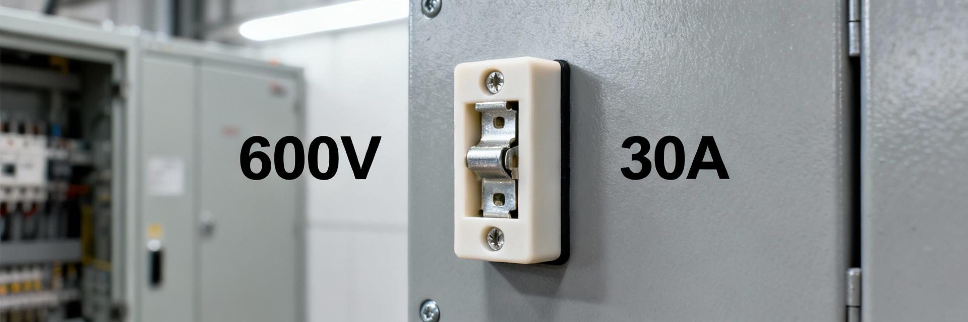
| Voltage Rating | 600 V |
| Current Rating | 30 A |
| Dielectric Strength | ~4000 V |
| Fuse Size Support | 10.3 mm × 38 mm (Midget) |
| Termination Type | Quick-Connect |
| Operating Temp Range | Down to approximately −40 °C min |
Voltage & Amp Limits: Data Breakdown
Voltage Rating Explained
The 600 V rating describes the maximum system voltage for intended use. While AC systems utilize nominal RMS ratings, DC systems may present different arcing behaviors. The 4000 V dielectric strength indicates the minimum hipot test passed, helping engineers establish safe isolation margins and transient withstand capabilities.
Current Rating & Thermal Limits
The 30 A mark is the holder’s continuous current reference. Note that continuous handling differs from surge performance; fuse selection (fast-blow vs. time-delay) significantly impacts thermal duty. Engineers should apply derating for high ambient temperatures and grouped installations to maintain contact integrity.
Installation, Mounting & Termination Best Practices
Panel-Mount & Clearance
Maintain specified clearances and respect torque for mounting hardware to prevent housing stress. Ensure orientation allows for natural convective cooling to minimize heat accumulation near adjacent devices.
Wiring & Termination
Use properly sized quick-disconnects (AWG 10 recommended for 30 A). Apply proper crimping with approved dies and ensure strain relief is present. Secure terminations prevent high contact resistance and localized overheating.
Safety, Testing & Derating Guidelines
Critical Safety Note: Perform hipot testing at values at or above the spec sheet figure during commissioning. Measure temperature rise at rated current; expected behavior involves stable contact resistance within published allowances.
Derating extends reliability in stressed environments. Reduce allowable continuous current or increase margins when ambient temperatures exceed reference points or when multiple heat-producing devices are closely grouped. Periodic infrared scans are recommended to identify potential hotspots before failure occurs.
How to Choose, Inspect & Maintain
- Confirm system voltage (AC or DC).
- Identify expected peak and continuous currents.
- Select compatible 10.3 x 38mm midget fuses.
- Ensure holder rating ≥ system needs (with margin).
- Verify termination compatibility with wiring.
Replacement Procedure
- De-energize the circuit and verify zero-voltage.
- Remove and replace with the correct-rated fuse.
- Inspect for discoloration or arcing marks.
- Torque hardware to spec and log the maintenance action.
Summary
The 05710008L is rated for 600 V and 30 A with a 4000 V dielectric strength. For maximum reliability, adhere to datasheet limits, apply necessary derating for high-temperature environments, and maintain regular inspection cycles to prevent heat-related degradation.
Common Questions (FAQ)
▶ What voltage and current is the 05710008L rated for?
The datasheet specifies a 600 V system rating and a 30 A continuous current capability, with dielectric/hipot figures near 4000 V. Use these figures as your baseline for system compatibility.
▶ Which fuse sizes are compatible with this holder?
This holder accepts midget cartridge fuses (approximately 10.3 mm × 38 mm or 13/32" × 1-1/2"). Always use the exact dimensions specified to ensure secure retention and contact.
▶ How should I derate the holder for high ambient temps?
Derate based on the delta between your operating ambient and the datasheet reference temperature. When holders are grouped or ventilation is restricted, reduce the allowable continuous current and verify thermal behavior via infrared imaging.
