The LM317T datasheet is a compact source of critical design numbers that translate directly into safety margins, heatsinking choices and test procedures; despite the prevalence of switching regulators, this three-terminal linear remains common on benches and in legacy products. Typical headline specs to preview: Vref ≈ 1.25 V, adjustable output range ≈ 1.25–37 V, rated current >1.5 A (with adequate dissipation), and typical dropout ≈ 2 V — use these as first-order design anchors.
Understanding the LM317T datasheet: key specs at a glance (contains main keyword)
Electrical specifications you must read
Point: The regulator’s electrical specs drive resistor selection and margin calculations. Evidence: the published Vout formula is Vout = Vref × (1 + R2/R1) + Iadj×R2; datasheet tables separate typical from guaranteed numbers. Explanation: pick R1 ≈ 240 Ω to keep Iadj error small, expect Iadj in the 50–100 μA range, Vref ≈ 1.25 V typical; verify the datasheet’s guaranteed Vref tolerance, dropout (≈2 V typical), max output current (>1.5 A) and idle/quiescent currents before finalizing component choices and the minimum Vin = Vout + dropout + margin.
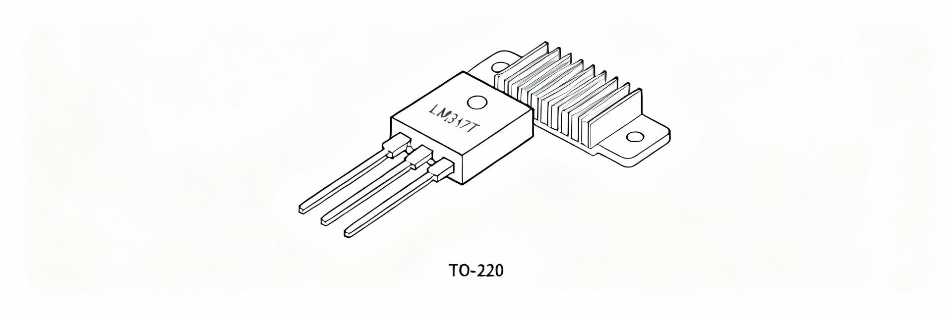
Thermal, packaging and environmental specs
Point: Thermal numbers set continuous current limits in practice. Evidence: datasheets list θJA/θJC, Tmax and derating curves for TO‑220 packages. Explanation: compute power dissipation Pd = (Vin − Vout) × Iout; then predict junction rise: Tj = Ta + Pd × θJA. For example, if Pd = 5 W and θJA = 50 °C/W, junction rises 250 °C above ambient — so add a heatsink. Use derating tables in the datasheet and choose a heatsink to keep Tj below the device’s maximum junction temperature with margin.
Datasheet test conditions & typical performance (interpreting graphs and tables)
How manufacturers measure the specs (test conditions)
Point: Test setups determine whether “typical” curves apply to your board. Evidence: datasheet graphs note test points (ambient temp, specific load steps, frequency for PSRR). Explanation: typical curves are often measured at 25 °C and with short leads; guaranteed specs use defined limits. Checklist: compare your ambient, board copper, lead lengths and load waveforms to the datasheet test conditions before accepting typical numbers for margin calculations.
Reading and using the characteristic curves: PSRR, load regulation, temp drift
Point: Curves convert published specs into simulation inputs. Evidence: line/load regulation, transient and PSRR graphs show magnitude vs. frequency or current step. Explanation: extract DC load regulation slope and transient overshoot numbers to size output caps and compensation; use PSRR at the frequency band of interest to estimate required input filtering. Always translate plotted “typical” curves into conservative design numbers for worst-case operation.
LM317T datasheet test limits & real-world stress (limits) (contains main keyword)
Absolute maximum ratings and safe operating area
Point: Absolute ratings and SOA define hard cutoffs. Evidence: datasheet lists maximum input voltage (commonly ~40 V), maximum junction temp, and current/power limits. Explanation: the LM317T’s thermal and power constraints create an SOA that can be exceeded with high Vin + high Iout. Compute Pd and compare to the datasheet’s power/temperature derating to find safe continuous current; if Pd or Tj exceed limits, add heatsinking or reduce continuous load.
Failure modes and “limits” that matter in the field
Point: Thermal shutdown, current limit and dropout define common failures. Evidence: datasheet describes built‑in current limiting and thermal protection behaviour. Explanation: realistic failure scenarios include sustained high Vin at high Iout, repetitive transients and shorts. Recommended margins: treat the regulator’s stated max current as conditional — derate continuous current by ~20–50% depending on ambient and heatsink capability, and log temperature/current during qualification to detect thermal foldback or drift.
Practical test methods: bench procedures to verify LM317T specs
Step-by-step bench tests to validate datasheet claims
Point: Structured bench tests confirm that your board meets datasheet expectations. Evidence: standard measurements—Vref, dropout, load regulation, transient—are repeatable when instrument setup follows rules. Explanation: test steps: 1) measure Vref between output and adjust at no load; 2) set Vout and sweep Iout to measure load regulation; 3) increase Iout and find dropout voltage; 4) apply step loads and record transient. Required instruments: stable supply, precision DMM, electronic load or resistor bank, and scope for transients. Define pass/fail margins tied to the datasheet guaranteed specs.
Reproducible setups and common gotchas
Point: Measurement artifacts often masquerade as device defects. Evidence: wiring inductance, poor sense points and absent decoupling change results from datasheet curves. Explanation: use low‑impedance grounding, place bypass caps per the datasheet close to pins, use Kelvin sensing where possible, and avoid long leads on the adjust network. Common fixes: add recommended input/output capacitors, shorten leads, and account for Iadj when using large R2 values.
Design checks, application examples & troubleshooting checklist
Quick design checklists and example circuits
Point: A concise checklist prevents late-stage surprises. Evidence: derived from specs-to-practice conversions. Explanation: checklist: verify Vin margin (Vout + dropout + margin), calculate Pd, choose heatsink to meet Tj limits, select R1 ≈ 240 Ω and cap values per datasheet, and include input filtering for PSRR. Examples: adjustable bench supply (add pre-regulator and large heatsink), simple current limiter (use LM317 configured as current source), and low‑noise reference (use low-ESR caps and short adjust lead).
Troubleshooting flow: diagnosing out-of-spec behavior
Point: Systematic checks identify whether issues stem from wiring, thermal, or component limits. Evidence: failures typically map to voltage drop, thermal rise, or adjust offset. Explanation: stepwise: confirm input voltage under load, measure Vref and adjust resistor tolerance, check device temperature and compare to computed Pd, inspect for long leads or missing caps. If behavior matches datasheet limits (thermal foldback or current limit), consider redesigning for lower Pd or adding active protection.
Summary
Treat the LM317T datasheet as a toolbox: Vref, dropout, maximum current and thermal numbers are the key inputs to convert specs into safe real‑world designs; validate assumptions with simple bench tests before sign‑off. Run the bench checklist and confirm thermal margins under the intended worst-case load to avoid surprises in qualification.
- Vref and the Vout formula set resistor choices and error budgets; use R1 ≈ 240 Ω and expect Iadj ~50–100 μA when calculating precise outputs and tolerances.
- Always convert published dropout and current ratings into Pd = (Vin − Vout)×Iout, then use θJA/θJC to size a heatsink so Tj stays below limits.
- Compare datasheet test conditions with your board: PSRR, transient and load regulation curves are typical values and require conservative margins for field use.
- Use the step‑by‑step bench tests: measure Vref, dropout, load regulation and transient response with proper wiring and decoupling before production sign‑off.
FAQ
What are the critical parameters in the LM317T datasheet I should check first?
Check Vref value and tolerance, maximum output current rating, dropout voltage, thermal resistance (θJA/θJC) and maximum junction temperature. These determine resistor selection, minimum Vin, power dissipation and heatsink needs. Verify whether values shown are typical or guaranteed and apply conservative margins for continuous operation.
How can I reliably measure dropout and ensure my design meets the LM317T datasheet dropout spec?
Use a stable adjustable input supply and a programmable electronic load; set Vout, increase Iout and slowly lower Vin until Vout falls by a defined amount (e.g., 100 mV). Record the Vin−Vout at that point as the dropout. Keep leads short, use Kelvin sensing for Vout, and repeat at the intended operating temperature for accuracy.
When should I treat the LM317T datasheet current spec as unusable and pick another regulator?
If the continuous Pd required to support your desired Iout at the available Vin forces junction temperature above safe limits even with practical heatsinking, the part is not suitable. Also reconsider if you need higher efficiency, very low dropout, or enhanced thermal management — in those cases a low‑dropout linear or a switching regulator may be the better choice.
