Executive Insight: Lab aggregates and typical datasheet readouts show that small high-voltage multilayer ceramic capacitors exhibit measurable DC‑bias capacitance loss, a resonance in the low‑hundreds of MHz, and Q variations tied to ESR/ESL. Bench LCR and VNA sweeps on comparable 33pF 200V parts routinely report 10–40% capacitance reduction at rated bias and resonance between 100–700 MHz.
Component Overview — 0505P330GP201X at a Glance
Key Specifications (Datasheet Extraction)
Before testing, a concise specification set is required to compare in‑circuit behavior to the datasheet baseline. These fields constrain test conditions such as bias, temperature, and mechanical stress.
| Field | Template Value |
|---|---|
| Nominal Capacitance | 33 pF |
| Tolerance | ±X % |
| Rated Voltage | 200 V DC |
| Dielectric / Temp Coeff. | P90 |
| Package Size | 0505 (≈1.2–1.4 mm) |
| Operating Temperature | -XX to +XX °C |
| Compliance | RoHS, REACH |
Core Electrical Metrics for MLCCs
Capacitance Stability
Effective capacitance shifts with temperature and applied DC bias. P90 dielectrics exhibit specific temperature coefficients. Lab data indicates values can drop significantly as they approach rated voltage (200V).
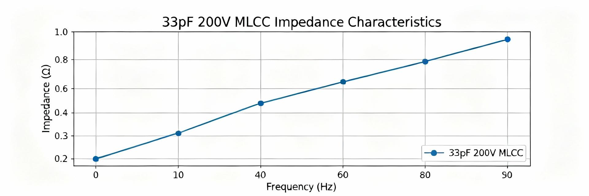
Frequency-Domain Metrics
Small 0505 MLCCs typically exhibit self‑resonance in the hundreds of MHz. Q peaks near resonance then falls due to ESR. Lower ESL is critical for broadband RF applications.
Measured Performance Deep-Dive
Recommended Benchmark Measurements
Reproducible characterization requires standardized sweeps. Essential measurements include impedance vs frequency (10 kHz–3 GHz), magnitude/phase, Q vs frequency, and capacitance vs DC‑bias (0–200V in steps).
Interpreting Results: Pass/Fail Signals
A capacitance collapse exceeding 30% at operating bias signals unsuitability for DC‑biased decoupling. For RF filtering, ensure ESL is low enough to keep resonance above the target operational band.
Methods Guide: Testing & Characterization
Lab Setup Best Practices
- • Use precision LCR meters for LF and VNAs for GHz impedance.
- • De-embed fixture parasitics via short/low-parasitic PCB setups.
- • Clean flux and ensure consistent soldering to avoid measurement drift.
Test Procedure Sequence
- Visual inspection and initial LCR at 1 kHz.
- RF sweep (10 kHz–3 GHz) at 0V.
- DC‑bias sweeps (0, 50, 100, 150, 200V).
- Thermal point testing (-40, 25, 85, 125°C).
Key Summary
- ✓ Verify Capacitance Under DC Bias: Measure C vs DC for the 33pF 200V part to quantify in‑circuit loss and ensure reactance stability.
- ✓ Characterize Frequency Response: Capture impedance magnitude/phase and Q to identify self‑resonance and potential ESL/ESR degradation.
- ✓ Robust Test Procedures: Perform calibrated sweeps and thermal tests on multiple samples to report mean±stdev for procurement.
- ✓ Layout and Derating: Minimize trace length and ground stitching to reduce pulse stress and capacitance collapse risks.
